Why Your 4-20 mA Sensor Reads Wrong and How to Fix It
A 7-step 4-20 mA troubleshooting guide for field technicians, diagnose power supply, wiring, loop resistance, grounding, transmitter, and data logger faults.
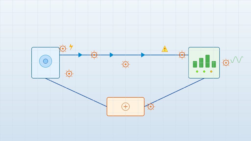
A sensor reading on the dashboard makes no sense. Stuck at 4 mA, jumping randomly, flat in the middle of range. Nine times out of ten, someone blames the sensor. Don’t start there. The 4-20 mA loop has several failure points between the transmitter and the data logger: power supply, cabling, connections, grounding, the transmitter itself, and the input configuration. The sensor is often fine; the problem is somewhere else in the loop.
This guide covers 7 sequential diagnostic steps that isolate an analog loop fault, from power supply all the way to signal interpretation. Think of it as the analog-signal companion to the Modbus RTU troubleshooting guide, which handles digital communication faults.
How a 4-20 mA current loop works in a monitoring system
A 4-20 mA loop has four parts: a sensor or transmitter, a twisted-pair cable, a loop power supply, and an analog input on a data logger or PLC. IEC 60381-1 defines 4 mA as the lower range value and 20 mA as the upper range value.
That’s the useful part of the live zero at 4 mA: you can tell the difference between a valid low-range reading (4 mA) and a broken wire or dead power supply (0 mA). In a two-wire setup, the transmitter draws its operating power from the loop current while modulating that same current to represent the measured variable, as described in the Texas Instruments TIDU299 reference design.
When any component in this loop fails or degrades, the data logger reading goes wrong. Even if the sensor is measuring the process correctly. The following seven checks help you find where.
Check 1: Verify the power supply
The power supply must deliver enough voltage to drive the transmitter and cover voltage drops across cable resistance and receiver input resistance. Basic requirement:
V_supply ≥ V_min_transmitter + (I_max × R_loop)
Measure voltage at the transmitter terminals while the loop is energized. Not just the open-circuit voltage at the supply. I’ve seen a 24 V supply deliver under 18 V at the transmitter after a 300-meter cable run. That’s enough to starve most transmitters.
Check 2: Inspect wiring and connections
Walk the entire cable path from transmitter to data logger. Look for corrosion, loose terminals, moisture ingress, or physical damage at junction boxes and terminal strips. In tropical environments (Indonesia, Southeast Asia in general), corrosion at terminal blocks can develop in months, not years. Humidity does real damage to exposed connections, especially at outdoor monitoring stations with poor gland seals.
Run a continuity test on both conductors. Then measure insulation resistance to catch leakage between conductors or to ground. A cable that tests fine for continuity but has low insulation resistance will cause readings to drift or bounce around erratically.
Check 3: Measure total loop resistance
Total loop resistance is the sum of transmitter internal resistance, cable resistance (both conductors), and receiver input resistance. If this total exceeds the transmitter’s maximum load resistance, the output saturates. The reading gets stuck at the bottom or top of range.
Maximum cable distance depends on wire gauge and the loop resistance budget: (V_supply − V_min_transmitter) ÷ 0.020 A = maximum total resistance. For remote monitoring stations with long cable runs, verify this calculation during installation. Don’t skip it. The sensor cable selection discussion in the 4-20 mA vs RS-485 article covers loop resistance budgets in more detail.
Check 4: Check grounding and shielding
Ground loops and electromagnetic interference (EMI) superimpose noise on the 4-20 mA signal. The result: readings fluctuate erratically or drift with no real process change. Ground cable shields at one end only, typically at the data logger, to prevent ground loop currents.

Industrial EMI from nearby motors, VFDs, and power cables is a common noise source. So is lightning-induced transient voltage at exposed outdoor stations. The grounding and EMI noise article covers shield termination and noise mitigation techniques for monitoring stations in detail.
Check 5: Measure the transmitter output directly
This is the single most useful step in 4-20 mA troubleshooting. Disconnect the loop at the data logger input and measure the mA output with a calibrated loop meter. If the transmitter produces the correct current but the data logger shows a wrong reading, the problem is in the wiring or data logger configuration. Not the sensor.
If the transmitter output is already wrong when measured directly, focus on the sensor itself, transmitter calibration, or the process connection (for example, a blocked impulse line on a pressure sensor). This one measurement splits the problem in half.
Check 6: Verify data logger input configuration and scaling
Confirm that the data logger channel is set for 4-20 mA input (not 0-10 V or digital). Check that the engineering unit mapping and range match the sensor output. One common mistake is double-scaling: applying scaling both in the transmitter and in the data logger. This produces a wrong engineering value even when the mA signal is correct.
Data loggers like the GEOVOS 1000 support 4-20 mA analog inputs. Verify the scaling configuration against the sensor datasheet whenever you change the setup. The 4-20 mA vs RS-485 article discusses range mapping fundamentals for analog sensor integration.
Check 7: Interpret diagnostic signal levels
Readings outside the normal 4-20 mA range carry diagnostic information. NAMUR NE 43 recommends treating signals below approximately 3.6 mA or above approximately 21 mA as fault conditions, not measurement values.
Common signal-level indicators:
- 0 mA: broken wire or loop has no power at all
- Exactly 4.00 mA: sensor at its lower range, transmitter in error mode, or process connection obstructed
- Below 3.6 mA (not zero): low fault, transmitter signaling an internal problem
- Above 21 mA: high fault, transmitter signaling an overrange condition or failure
Knowing these patterns prevents a common mistake: treating a fault signal as a real measurement, or swapping out a sensor when the actual problem is a dead power supply. For context on how data quality flags relate to loop anomalies, see the sensor data quality guide.
When to call for integration support
If you’ve run all seven checks and the problem won’t go away, or if multiple sensors show similar faults at the same time, the issue is probably system-level: loop design, power supply compatibility, data logger configuration, or the data path from field to dashboard. At that point, stop chasing individual components.
Fortuna Argatech can review loop design, wiring, sensor configuration, data logger scaling, and data paths in monitoring systems. Reach out through the contact page for technical consultation.
Share this article
Share this insight with your team.
Related Articles
Similar topics from the same category.

Poor weather station placement can cause 50% data bias. Learn the WMO-No. 8 and Indonesian BMKG siting standards for AWS sensors in industrial and mining sites.

Explore a technical engineering comparison between solid-state ultrasonic anemometers and mechanical cup-and-vane sensors for industrial weather stations.

Technical guide to conductivity sensors: comparing toroidal (inductive), 2-electrode, and 4-electrode contacting probes for industrial water and wastewater.