4-20 mA vs RS485: Which Sensor Output Fits Your System?
A practical guide to matching industrial sensor output with the receiving system, diagnostics, wiring, failure behavior, and commissioning.
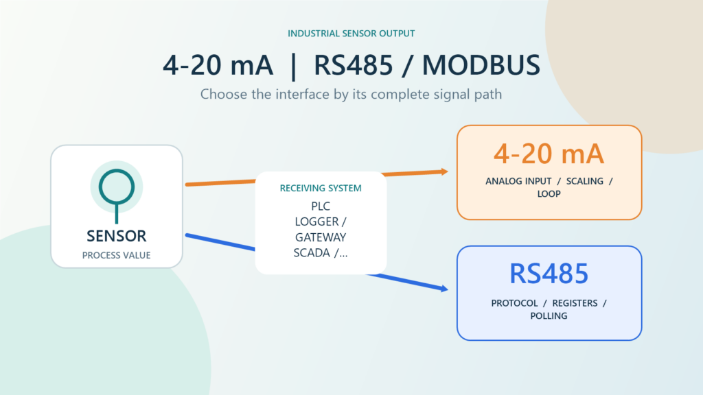
4-20 mA vs RS485 should be decided by how the system will read, diagnose, and use sensor data, not by assuming one interface is always more modern. For one process value entering an existing PLC or data-acquisition analog channel, 4-20 mA is often a direct and traceable path. When the system needs several values, device status, or communication with multiple sensors on a bus, RS485 with a defined protocol may be the better fit.
Either choice can fail when the integration details are incomplete. An analog loop needs correct scaling, power, load, isolation, and alarm behavior. A serial network needs a protocol, register map, address, data format, polling rules, and a sound physical design. The useful question is whether the complete signal path can be explained from the sensor to the consuming application.
Fortuna Argatech publishes 4-20 mA and RS485/Modbus output options for several sensor families, including the Radar Level Meter, Rika RKL-03, and Liquid Level Transmitter. The GEOVOS 1000 Datalogger page lists an RS485 sensor interface. These pages establish possible integration paths, but the ordered configuration and final compatibility still have to be confirmed for each project.
4-20 mA vs RS485: the differences that matter
The most useful comparison is not simply analog versus digital. It is a comparison of the responsibilities that the entire signal chain must fulfill. Use this table as a pre-datasheet screening tool.
| Area | 4-20 mA | RS485 with a protocol such as Modbus RTU |
|---|---|---|
| Data form | Current magnitude represents one primary analog value in a basic loop | Digital frames can carry values, status, or multiple registers exposed by the device |
| Receiver | A compatible analog input and engineering-unit scaling | An RS485 port plus a driver or protocol implementation that understands the device messages |
| Data identity | Established by the channel, wiring, and I/O documentation | Established by device address, function, register, data type, and protocol documentation |
| Adding points | Usually requires another loop and input channel | Several devices may share a bus when capacity, topology, addressing, and polling time allow it |
| Troubleshooting | Check loop current, power, wiring, input, scaling, and alarm limits | Check the physical bus, serial settings, address, response, exception, timeout, and data freshness |
| Configuration risk | Mismatched sensor and input ranges, incorrect power or polarity, or insufficient loop budget | Wrong register map, byte or word order, duplicate addresses, mismatched serial settings, or stale data treated as current |
| Good starting point | One process variable, an available analog channel, and point-by-point separation | Multiple values or status are needed and the team can own the serial integration and network |
This table does not mean that every device behaves the same way. Cable selection, distance, device count, termination, isolation, and protection must follow the selected equipment documentation and actual site conditions.
When does 4-20 mA make more sense?
In a basic analog loop, the receiver converts current into an engineering value using defined scaling. The lower and upper sensor ranges are mapped to the lower and upper input values. A Texas Instruments loop-powered 4-20 mA transmitter reference design illustrates one common two-wire arrangement: the transmitter uses the loop terminals and controls return current to a host analog input. It is a representative architecture, not a universal wiring rule for every 4-20 mA instrument.
4-20 mA is a sensible starting point when the system needs one principal variable from each sensor, the PLC or data-acquisition system already has a suitable analog input, and point-to-point traceability is valuable. Separate loops can also help field work because a technician can measure and isolate one channel without interpreting traffic from the entire bus.
That simplicity depends on completing the loop design. The team still needs to align sensor range, input range, units, resolution, power source, polarity, total load, isolation, grounding, and alarm rules. A plausible current does not prove the physical measurement is correct; a sensor can be stuck, the process connection can be obstructed, or the scaling can be wrong. Reference checks and controlled fault tests remain part of commissioning.
When do RS485 and Modbus fit better?
RS485 becomes attractive when one device exposes more than one value, diagnostic status, counters, or configuration parameters that the system genuinely needs. A serial bus may also reduce the need for a dedicated signal pair for every variable, but the benefit only appears when topology, capacity, response time, and maintenance are designed properly.
Keep the terminology separate. The Modbus Organization explains that Modbus is a process-data exchange protocol defining commands, addressing, and data formatting, while the physical network can use several technologies, including EIA/TIA-485. An RS485 label on a datasheet therefore does not prove that a device uses Modbus RTU. It may use another protocol or a vendor-specific message format.
Ask for the exact protocol document before choosing the interface. Integration normally needs the device address, baud rate, parity, stop bits, function codes, registers, data types, signed or unsigned interpretation, multipliers, units, byte order, word order, polling interval, timeout, and meaning of exception values. The Modbus Specifications page also separates obsolete serial material from the current implementation guide for new serial applications. These details matter more than a generic digital output label in a quotation.
For a separate introduction to the bus and protocol relationship, see RS485 Modbus: Why So Many Sensors Use It. Procurement and commissioning should still use the manual for the exact model and firmware being installed.
Design failure handling before selecting the output
A useful interface must do more than deliver a number while every component is healthy. The design needs a clear response to a broken cable, lost sensor power, stopped serial responses, unchanged measurements, gateway restarts, and configuration changes.
For 4-20 mA, agree on valid limits, alarm limits, and the action taken when current falls outside the expected condition. Confirm that both the transmitter and receiving input support the intended behavior; do not assume every device uses the same fail direction. Decide whether the last value may remain visible, must carry a quality marker, or should trigger an operator check.
For RS485/Modbus, a valid frame does not prove that the physical measurement is fresh or correct. The receiver should maintain timestamps, timeout limits, communication status, and rules for the last good value. Commissioning should include controlled tests for a disconnected bus, wrong address, delayed response, device restart, and register values outside logical limits. The result should be handled consistently by the PLC, datalogger, dashboard, alarms, and reports.
When should you consider a hybrid architecture?
A project does not have to force one interface onto every sensor. Some points may use 4-20 mA because they connect directly to a PLC, while others use RS485 because they expose multiple parameters or gather at a datalogger. When a device offers two output options, plan simultaneous use only if the exact datasheet and model testing confirm that mode.
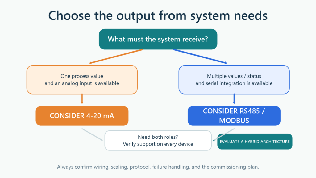
A hybrid architecture also needs an agreed source of truth. If the same value is available through two paths, define which path drives control, history, alarms, and validation. Avoid two values with different scaling or timestamps that are both treated as authoritative. Document who may change the analog range, address, registers, or gateway configuration.
Eight questions to answer before issuing a purchase order
- What must the system receive? Decide whether one process value is enough or whether status, multiple parameters, configuration, and device diagnostics are required.
- Which device receives the signal? Match the output to the actual PLC analog input, remote I/O, data-acquisition unit, datalogger, or gateway.
- Does the published option match the quoted configuration? Request the model code, wiring diagram, manual, and firmware revision. Do not assume that two listed options operate simultaneously.
- How is the data interpreted? For analog, define range and units. For digital, lock down the register map, data type, scaling factor, byte or word order, and special values.
- How will failures be recognized? Specify the response to cable breaks, lost sensor power, unchanged values, timeouts, duplicate addresses, gateway restarts, and stale data.
- Has the electrical and cabling design been checked? Review power, load, isolation, grounding, protection, routing, topology, termination, and the installation environment against selected-device documentation.
- What proves compatibility before full deployment? Run a bench test or pilot using the planned sensor, cable, input, converter, gateway, and software versions.
- What is handed over after commissioning? Require the I/O list, loop diagrams, network drawing, configurations, register map, backups, test records, alarm list, and device-replacement procedure.
These questions make quotation comparisons more realistic. A device price can look low while uncounted converter, engineering, troubleshooting, and documentation work moves the cost into integration.
Fit the interface to the architecture
The final choice should follow the function, receiving system, failure behavior, maintenance capability, and expansion plan. If the data path cannot yet be drawn clearly from the sensor to the user, selecting the output is premature.
Fortuna Argatech can help review measurement requirements, I/O lists, protocols, datalogger or gateway roles, connectivity, dashboards, and the test plan as one system. To discuss available configurations and integration boundaries, contact the Fortuna Argatech team with the sensor datasheet and details of the intended receiving equipment.
Technical sources
- Low Cost Loop-Powered 4-20mA Transmitter, EMC/EMI Tested Reference Design, Texas Instruments, October 2014.
- An Introduction to Modbus, Modbus Organization.
- Modbus Specifications, Modbus Organization.
Share this article
Share this insight with your team.
Related Articles
Similar topics from the same category.

Poor weather station placement can cause 50% data bias. Learn the WMO-No. 8 and Indonesian BMKG siting standards for AWS sensors in industrial and mining sites.

Explore a technical engineering comparison between solid-state ultrasonic anemometers and mechanical cup-and-vane sensors for industrial weather stations.

Technical guide to conductivity sensors: comparing toroidal (inductive), 2-electrode, and 4-electrode contacting probes for industrial water and wastewater.