Data Logger vs PLC: Which Fits Monitoring or Control?
Compare data logger vs PLC roles in monitoring, local control, storage, communications, integration, and hybrid architectures before specifying a system.
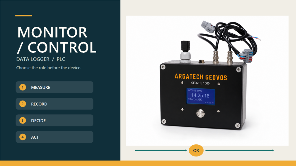
Data logger vs PLC selection should begin with the system’s primary responsibility: record and report measurements, control a local process, or do both. When the main need is to collect field data from a remote location, retain it, and display it on a dashboard, a data logger is often the more direct starting point. When the system must execute logic, interlocks, operating sequences, or actuator commands locally, a PLC usually carries the primary role.
The two devices are not always substitutes. A PLC may expose data to a historian or Supervisory Control and Data Acquisition (SCADA) system, while a modern data logger may include processing and communications. The safer question is not which device sounds more advanced. It is which device owns each function and what happens when a sensor, network, server, or connected device fails.
Fortuna Argatech works with telemetry, remote monitoring, and industrial integration. In that context, the published GEOVOS Datalogger 1000 provides an example with 4G connectivity, an RS485 sensor interface, 8 GB of local storage, a monitoring platform, and WhatsApp or email notifications. For automation projects, the Fortuna Argatech Industrial Solution page also lists integration with existing PLC and SCADA systems through industrial protocols such as OPC-UA. These pages describe different capabilities; they do not establish GEOVOS itself as a PLC or an OPC-UA endpoint.
Data logger vs PLC: separate their primary responsibilities
USGS guidance for measurement stations describes an electronic data logger as a device that can record variables on a regular or user-defined schedule, then store or transmit the resulting data. NIST SP 800-82 Rev. 3, by contrast, places PLCs in the local-control layer and describes functions such as I/O control, logic, timing, counting, PID, communications, and data processing.
Those responsibility boundaries are more useful than product labels.
| Area | Data logger as the starting point | PLC as the starting point |
|---|---|---|
| Primary job | Acquisition, time-stamped recording, storage, and data transmission | Local control logic, sequencing, interlocks, and input-output management |
| Typical path | Sensor to logger, network, server or cloud, dashboard, and user | Sensor or input to PLC logic, then output or actuator; selected data may continue to HMI, SCADA, or a historian |
| External network outage | Local measurements may continue when configuration and storage support it; synchronization behavior must be demonstrated | Local control may continue according to the design without an external dashboard; failure behavior still needs to be defined |
| Storage and reporting | Usually central to the design | May be built in or delegated to a historian or SCADA layer, but is not the main reason to choose a PLC |
| Configuration changes | Commonly focuses on channels, intervals, calculations, communications, and reporting | Requires control-program, I/O, interlock, and change-management discipline |
| Core acceptance question | Is the data complete, time-stamped, retained, and delivered to the right user? | Does the process remain in its designed state and do outputs respond correctly to the logic? |
This comparison does not mean every data logger or PLC has the same feature set. A particular model may cross the boundary. Specifications still need to be matched to I/O, protocols, response times, environmental conditions, retention requirements, and operating procedures.
Use a data logger when the decision centers on data
A data logger is a strong architectural center when a team needs to acquire sensor parameters, assign timestamps, preserve history, transmit data, and make it available for analysis or notifications. This pattern is common in environmental, hydrological, weather, structural, water-quality, energy, and distributed-asset monitoring where complex machine control is not the primary task.
Begin with data quality rather than the longest feature list. How many channels and signal types are required? Do the sensors use analog, pulse, serial, or a named protocol? What are the sampling and logging intervals? How long must records remain available without communications? How is the clock synchronized? Who receives notifications or reports? How are anomalous records identified and compared with a reference?
The safe capabilities shared by the Indonesian and English GEOVOS pages are 4G, RS485, 8 GB storage, the monitoring platform, and WhatsApp or email notifications. Storage retention cannot be inferred from capacity alone because it depends on the number of parameters, record format, and interval. Storage also does not by itself prove that every record will be resent without loss after connectivity returns. Buffering, synchronization, duplicates, and timestamp order must be confirmed in the design and demonstrated during commissioning.
If the sensor interface is RS485, do not stop at the interface name. Check the protocol, device addressing, register map, data types, termination, cable topology, grounding, and isolation. The Fortuna Argatech article on RS485 Modbus provides useful background, but final compatibility still needs to be tested with the selected sensor and device.
Use a PLC when the system must act locally
A PLC is the clearer center when inputs must produce defined local actions: run a pump, position a valve, sequence machinery, maintain a set point, apply an interlock, or move the process to a designed state during a fault. NIST explains that PLCs can operate as local controllers within SCADA or Distributed Control System (DCS) architectures, or as the primary controller in smaller Operational Technology (OT) configurations.
A PLC project therefore needs different engineering artifacts from a data-logging project. The team should prepare an I/O list, control narrative, cause-and-effect or interlock matrix, manual and automatic modes, signal-loss behavior, access roles, program version control, backups, and a Management of Change procedure. Safety functions require devices, standards, and verification selected for that purpose; the PLC label alone does not establish certification or a safety-integrity level.
A PLC can also send records to an HMI, SCADA system, historian, or another platform. Built-in logging does not complete the reporting architecture, however. Retention, timestamps, data quality, historical resolution, remote access, and recovery after a communications failure still need explicit design decisions.
Choose a hybrid architecture when monitoring and control both matter
Many systems should not force one device to perform every role. The PLC can continue to control the local process while a data logger, gateway, or SCADA layer collects approved variables for retention, dashboards, reports, and remote notifications. In another design, a data logger may handle independent environmental sensors and exchange selected data with the control system.
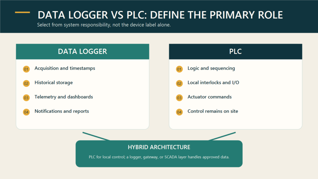
A hybrid design needs an explicit responsibility boundary. Which device is the source of truth? Where are timestamps generated? Is data read from the sensor or from the PLC? What happens when the link between devices fails? Can a dashboard outage affect local control? Who is allowed to change programs, registers, thresholds, or communications settings?
The Fortuna Argatech Industrial Solution page publishes integration capability for existing PLC and SCADA systems through industrial protocols, including OPC-UA as an example. This supports a solution-level integration discussion, but the actual interface must be verified against the selected equipment. Do not assume that GEOVOS provides OPC-UA or control functions merely because the wider company portfolio includes integration services.
Seven questions to answer before requesting a proposal
- Which functions must continue when the internet or central server is unavailable? Separate local control from remote visibility.
- Does the system only read sensors, or does it also command actuators? An output list and control narrative often reveal the PLC requirement.
- Which signals and protocols are actually available? Request the I/O list, datasheets, register maps, and network diagram.
- What history and reporting are required? Define interval, retention, timestamping, export, audit trail, and data-recovery behavior.
- How should each failure be handled? Cover sensor faults, out-of-range values, network loss, power loss, full storage, and unavailable servers.
- Who manages changes and security? Separate operator, engineer, administrator, and vendor permissions; document backups and approvals.
- How will the system be tested and maintained? Define Factory Acceptance Test, Site Acceptance Test, commissioning, reference checks, communication-failure tests, and handover records.
These answers are usually more useful than asking a vendor to choose a device from the sensor count alone. Fortuna Argatech can help map measurement points, control requirements, I/O, communications, storage, dashboards, and integration with existing systems. Begin with a process description, point list, network diagram, reporting requirement, and intended failure states so that a data logger, PLC, or hybrid recommendation can be defended.
Technical references
- National Institute of Standards and Technology, Guide to Operational Technology (OT) Security, NIST SP 800-82 Rev. 3, September 2023.
- U.S. Geological Survey, Stage Measurement at Gaging Stations, Techniques and Methods 3-A7, 2010.
- Fortuna Argatech, GEOVOS Datalogger 1000 and Industrial Solution pages, accessed July 24, 2026.
Share this article
Share this insight with your team.
Related Articles
Similar topics from the same category.

Poor weather station placement can cause 50% data bias. Learn the WMO-No. 8 and Indonesian BMKG siting standards for AWS sensors in industrial and mining sites.
Explore a technical engineering comparison between solid-state ultrasonic anemometers and mechanical cup-and-vane sensors for industrial weather stations.

Technical guide to conductivity sensors: comparing toroidal (inductive), 2-electrode, and 4-electrode contacting probes for industrial water and wastewater.