Grounding and EMI Noise Control for Monitoring Stations
Practical grounding monitoring station guide — from EMI interference paths to single-point topology and commissioning verification.
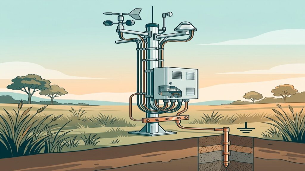
The sensor is calibrated, the cables are routed to specification, yet the dashboard shows random spikes or unexplained drift. More often than not, the problem is not the sensor — it is how the monitoring station is grounded. Signal noise, measurement drift, and phantom spikes can originate from grounding errors and electromagnetic interference (EMI) rather than from sensor hardware faults.
Grounding appears across many monitoring system topics — from sensor cable selection to lightning protection and system commissioning. Yet no single guide consolidates grounding design, shield-connection rules, ground-loop prevention, and EMI noise control into one practical framework for monitoring stations. This article provides that framework.
How EMI Enters a Monitoring Station
EMI reaches monitoring equipment through three coupling paths. Conducted coupling travels along power and signal cables that connect directly to instruments. Radiated coupling occurs when nearby electromagnetic fields are picked up by cables acting as unintentional antennas. Common-impedance coupling arises when different devices share the same ground return path, causing voltage differences at measurement points.
Long sensor cable runs increase exposure to radiated EMI because longer cables capture more interference energy. In a monitoring station context, common EMI sources include cellular modems, solar charge controllers, and nearby industrial equipment. Understanding these three coupling paths is essential before designing the grounding architecture, because each mechanism requires a different mitigation approach.
Signal Grounding vs. Safety Grounding: Why the Distinction Matters
Many technicians assume that the lightning grounding rod on the station mast is sufficient to prevent sensor noise. In practice, safety grounding (protective earth) and signal-reference grounding serve different functions.
Safety grounding provides a fault-current and lightning-discharge path to earth, protecting personnel and equipment. The lightning protection article covers the protection chain from air terminal through to the earthing system.
Signal-reference grounding establishes a stable voltage reference so that the data logger and sensors measure from the same baseline. Without a clean signal reference, small potential differences between ground points appear as noise in sensor readings.
Equipotential bonding connects all metallic parts — mast, enclosure, DIN rail, cable shields — to a single earth reference. This prevents potential differences that become noise sources. These three grounding functions complement each other but are not interchangeable — a lightning ground rod does not automatically provide a clean signal reference.
Single-Point Grounding and Ground-Loop Prevention
A ground loop forms when two or more ground connections create a closed circuit. Current flowing through this loop induces voltage differences that appear as measurement error. Ground loops are the most common noise source in multi-sensor monitoring stations.
Single-point grounding (star topology) routes all ground returns through one defined path, eliminating the loop. IEEE 1100 and Analog Devices recommend this approach for low-frequency instrumentation — which covers most environmental and industrial monitoring sensors.
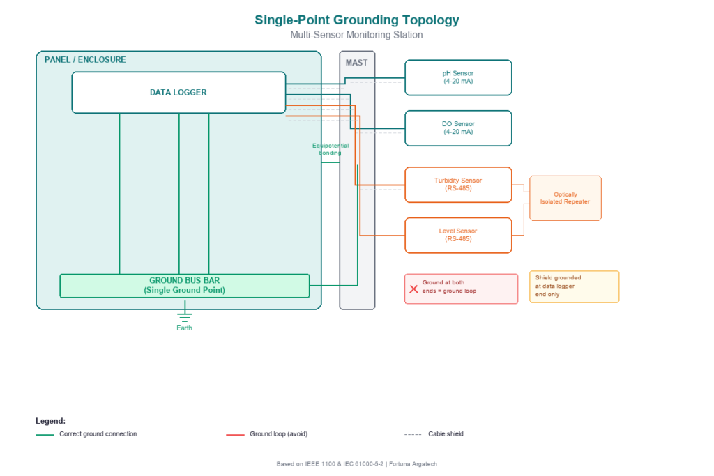
Practical application in monitoring stations:
- 4-20 mA signals: In loop-powered transmitters, the receiver (data logger) serves as the ground reference. Separate ground connections at both ends of the cable — transmitter and receiver — can form a ground loop. Maintain only one ground reference point per loop.
- RS-485 networks: In multi-drop RS-485 networks, devices at different locations may sit at different ground potentials. Optically isolated repeaters can prevent ground loops between network segments with differing ground potentials.
- Isolated inputs: Data loggers with galvanically isolated inputs break the ground-loop path between channels, providing additional protection in multi-sensor installations.
The choice between 4-20 mA and RS-485 affects the grounding strategy — consider the grounding architecture at the design stage, not as a fix after noise appears.
Cable Shield Grounding: One End or Both?
The default rule for sensor cable shield grounding: connect the shield to ground at one end only — typically the data logger (receiver) end. A single-end grounded shield drains interference to earth without creating a ground loop. The sensor cable selection guide covers cable types and shielding options per protocol.
An exception applies for very long cables (exceeding approximately 100 meters) or in environments with high-frequency interference. In these cases, grounding the shield at both ends through high-frequency bypass capacitors may be appropriate — but this requires case-by-case evaluation to avoid side effects.
Commissioning Verification for Grounding and Noise
Before a monitoring station goes live, grounding verification should be part of the commissioning checklist. Key verification steps:
- Measure earth resistance — use an earth tester to confirm resistance meets the design specification. Soil conditions change with seasons, so periodic measurement is necessary.
- Test shield continuity — verify that the shield connection is intact from cable end to ground point.
- Check for ground loops — measure DC voltage between ground points that should be at the same potential. A difference of more than a few millivolts indicates a potential ground loop.
- Record a noise baseline — capture noise readings during commissioning as a reference for future troubleshooting. If noise increases later, this baseline helps isolate the source.
When to Involve a System Integrator
Grounding design for a monitoring station with one or two sensors and short cable runs can typically be handled by an experienced field technician. But complexity increases in installations with:
- Multiple sensors (>4) using mixed protocols (4-20 mA and RS-485)
- Long sensor cables (>50 m) in areas with significant EMI sources
- Solar panels, cellular modems, and data loggers sharing one enclosure
- High-accuracy requirements for regulatory compliance (SPARING, AQMS)
Under these conditions, grounding design requires thorough analysis of the topology, separation of signal and power paths, and selection of equipment with appropriate isolation. Fortuna Argatech generally equips open-area monitoring station installations with grounding systems as part of the overall station design — whether for SPARING, ONLIMO, AWLR, AQMS, weather stations, or extensometers. If your monitoring station experiences noise that basic troubleshooting cannot resolve, contact the engineering team for a grounding and EMI evaluation.
Share this article
Share this insight with your team.
Related Articles
Similar topics from the same category.
Poor weather station placement can cause 50% data bias. Learn the WMO-No. 8 and Indonesian BMKG siting standards for AWS sensors in industrial and mining sites.
Explore a technical engineering comparison between solid-state ultrasonic anemometers and mechanical cup-and-vane sensors for industrial weather stations.

Technical guide to conductivity sensors: comparing toroidal (inductive), 2-electrode, and 4-electrode contacting probes for industrial water and wastewater.