Water Quality Sensor Installation: Submersible, Flow Cell, or Bypass?
Guide to choosing submersible, flow cell, or bypass installation for online water quality sensors based on sensor type and site conditions.
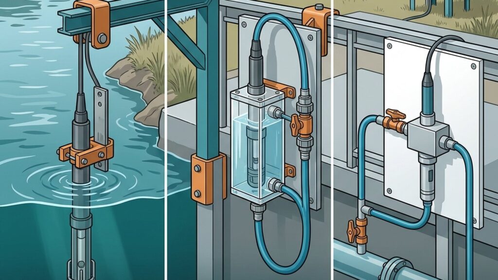
The same water quality sensor can deliver reliable or misleading data depending on how it is physically installed. Water quality sensor installation method determines fouling rate, maintenance access, response time, and whether the reading actually represents process conditions. ISO 15839 divides online water quality measurement into two categories: in-situ — where the sensor sits directly in the water body — and extractive, where a sample is brought to the sensor through piping or a flow cell. In field practice, these translate into three installation approaches: submersible, flow cell, and bypass.
Three Installation Approaches
Submersible (in-situ) places the sensor directly in the water body — a river, pond, treatment basin, or discharge channel. The sensor reads actual ambient conditions without pumps or piping.
Flow cell provides a controlled chamber where water flows past the sensor at a managed velocity. Water reaches the cell through a pump or gravity feed and returns to the process or water body.
Bypass sampling extracts a portion of water from the main process or water body through piping to a separate measurement point. The sensor is mounted in a panel or measurement chamber located outside the main water body.
Each method brings specific tradeoffs that must be evaluated before commissioning.
Submersible: Simple but Exposed
Submersible installation requires the least infrastructure — no pumps, no piping. The sensor directly reads temperature, pH, dissolved oxygen, or conductivity at actual conditions in the measurement location.
The tradeoff: the sensor is directly exposed to debris, biological fouling organisms, and sedimentation. In still or slow-moving water, biofouling and sediment accumulation tend to accelerate compared to sensors exposed to moderate flow. For deep-water deployments, maintenance may require boats or divers — adding cost and access time.
Pontoon-mounted submersible installations are widely used for river monitoring where fixed overhead structures such as bridges are unavailable. Fortuna Argatech deploys this approach in ONLIMO river water quality monitoring systems.
Flow Cell: Controlled but Supply-Dependent
Flow cells reduce sensor exposure to large debris and variable currents. The controlled environment simplifies calibration access — a technician removes the sensor from the cell without entering the water body.
However, flow cells depend on a consistent water supply. If the pump fails or gravity flow is interrupted, the sensor measures stagnant water instead of current process conditions. The cell dimensions and flow rate must match the sensor probe size and the minimum flow velocity recommended by the sensor manufacturer.
A critical consideration for optical sensors: air bubbles trapped in a flow cell produce erroneous readings, particularly for turbidity, TSS, and dissolved oxygen sensors. The cell must be designed or installed to prevent air accumulation near the sensor membrane or optical window.
Bypass: Flexible but Delayed
Bypass sampling offers high flexibility — the sensor can be installed inside a closed panel, protected from weather and vandalism, with convenient maintenance access. This method becomes the only practical option when the measurement point is a pressurized pipe that does not allow direct submersible installation.
The primary tradeoff: sample transport through bypass piping takes time. The sensor reads conditions that existed at the extraction point some time earlier, not real-time conditions. During transport, water temperature, dissolved gas content, and particle suspension can change — potentially altering readings for DO, pH, turbidity, and other temperature-sensitive parameters.
Bypass piping also requires regular flushing and cleaning to prevent biofilm, mineral scale, or sediment buildup inside the sample lines.
Which Method Fits Which Sensor
Each water quality parameter has different installation preferences:
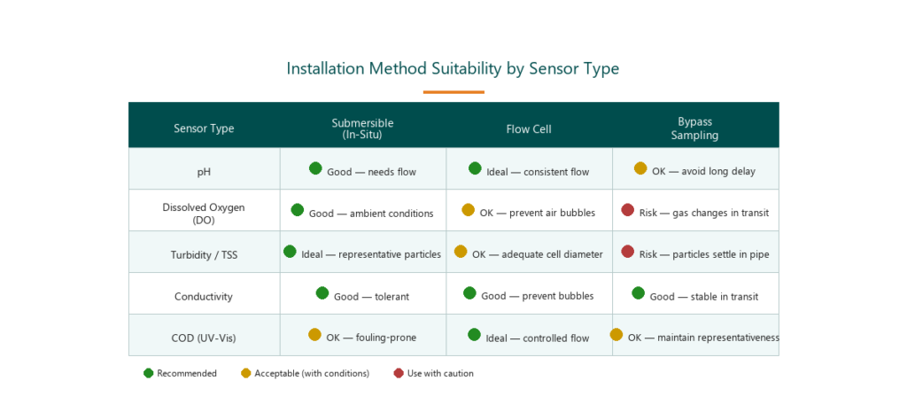
pH — pH sensors work across all three methods but benefit from sufficient water movement past the glass membrane to avoid stagnant-layer measurement artifacts. Flow cells provide the most consistent flow for continuous pH measurement.
Dissolved oxygen (DO) — DO sensors need representative water flow but are sensitive to air entrainment. If a flow cell is used, the design should prevent air bubble accumulation near the sensor membrane. Long bypass lines risk altering dissolved gas content before the sample reaches the sensor.
Turbidity and TSS — Optical turbidity and TSS sensors need a sample that represents the actual particle distribution. Long bypass lines, sharp bends, or low flow velocities may allow particles to settle before reaching the sensor — producing readings lower than actual values. Submersible deployment or large-diameter flow cells with adequate flow are generally more suitable.
Conductivity — Conductivity sensors are generally tolerant of different installation methods but can produce errors from air bubbles in the measurement cell or excessive turbulence around the electrodes.
Site Conditions That Drive the Decision
Beyond sensor type, field conditions determine which installation method is practical:
- Water body type: a debris-laden river, a calm pond, a process tank, or a pressurized pipe each constrain the available options differently.
- Debris and sediment load: sites with heavy floating debris or fine sediment accelerate fouling on submersible sensors.
- Maintenance access frequency: if the team can only visit monthly, a flow cell or bypass with panel access is more practical than a deep-water submersible deployment.
- Distance from compliance point: for regulatory compliance monitoring, the sensor should be installed at or near the designated compliance point. Moving the measurement far from the discharge through a long bypass line may raise questions about sample representativeness.
- Power and connectivity availability: bypass and flow cell systems require pumps (unless gravity pressure is available), adding power requirements.
- Environmental exposure: flood risk, vandalism potential, and UV exposure influence the choice between open installation (submersible) and protected installation (bypass panel).
Common Installation Mistakes
Several technical errors recur in field deployments:
- Insufficient flow velocity in a flow cell — the sensor measures stagnant water instead of current process conditions.
- Sensor too close to the water surface in submersible deployment — during low-water events, the sensor is exposed to air, which can damage optical windows or reference junctions.
- Sensor cables routed through flood zones without adequate protection — vulnerable to physical damage, water ingress, and total sensor failure.
When to Engage a System Integrator
Multi-parameter compliance monitoring systems (SPARING), river monitoring pontoon deployments (ONLIMO), and complex piping integrations require professional system design and installation. The right combination of sensor types, installation methods, connectivity, and data logging depends on site-specific conditions.
Fortuna Argatech provides technical consultation to help determine the appropriate installation configuration — from site survey through commissioning and operator training.
Share this article
Share this insight with your team.
Related Articles
Similar topics from the same category.

Poor weather station placement can cause 50% data bias. Learn the WMO-No. 8 and Indonesian BMKG siting standards for AWS sensors in industrial and mining sites.
Explore a technical engineering comparison between solid-state ultrasonic anemometers and mechanical cup-and-vane sensors for industrial weather stations.

Technical guide to conductivity sensors: comparing toroidal (inductive), 2-electrode, and 4-electrode contacting probes for industrial water and wastewater.