Dynamic Calibration of Tipping Bucket Rain Gauges: Correcting High-Intensity Rainfall Undercatch per WMO-No. 8
An engineering guide to correcting tipping bucket rain gauge undercatch dynamic calibration and datalogger polynomial algorithms.
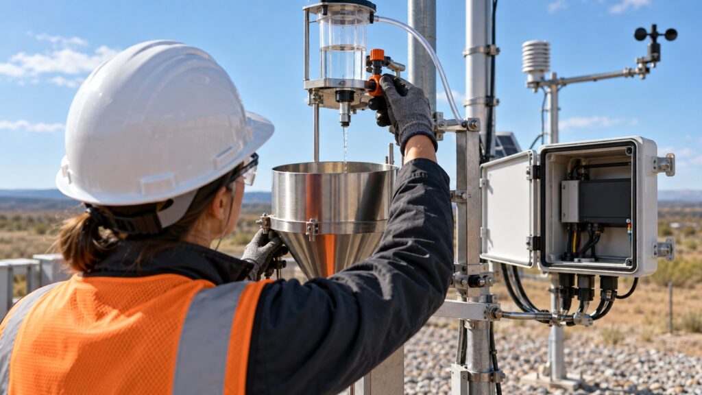
Does your automatic weather station (AWS) consistently record lower rainfall totals than the actual runoff flooding your site during a tropical storm? It is not an illusion. The tipping bucket rain gauge is the default precipitation sensor in industrial meteorology because it is mechanically simple. It converts water volume into a digital pulse. But that simplicity hides a severe mechanical bias. Conventional tipping buckets without software compensation drop the ball when it rains hard. They record lower-than-actual measurements, a flaw known as undercatch. Once rainfall intensity crosses 100 mm/h, undercatch can skew your data by 10% to 30%.
International standards EN 17277:2019 and WMO-No. 8 mandate that liquid rainfall intensity accuracy must be measured at a 1-minute resolution in millimeters per hour. Artificially low rainfall data ruins Intensity-Duration-Frequency (IDF) curve analysis. That bad math leads directly to undersized pit drainage networks and blown settling ponds. This engineering guide breaks down the physical mechanics of water loss during a bucket tip. It details EN 17277 and WMO-No. 8 testing standards. Most importantly, it explains how to execute proper tipping bucket dynamic calibration and run polynomial correction curves directly on edge telemetry dataloggers.
Static Calibration Pitfalls: Why Drop-by-Drop Tests Are Misleading in Tropical Climates
Field technicians typically perform a basic static calibration. They drip water into the gauge’s funnel incredibly slowly to keep the flow rate near zero. The goal is to adjust the mechanical stop screws so the bucket tips exactly at its static nominal volume, usually 0.2 mm per tip. This establishes a baseline. But static calibration only confirms the geometric holding capacity of the bucket when it is stationary. It is completely blind to the fluid dynamics of a severe thunderstorm.
The WMO-No. 8 guide explicitly identifies the problem. The primary source of mechanical error in tipping buckets during heavy rain is the loss of water that continues to pour from the funnel while the bucket is actively moving. Relying entirely on static calibration in a tropical environment is dangerous. An instrument will pass a slow workshop bench test perfectly but will fail massively during an actual storm. Engineers then design undersized drainage infrastructure based on those flawed historical records.
The Physics of Water Loss During Tipping: Transit Time Mechanism and Undercatch Bias
Static calibration fails because of mechanical transit time ($\Delta T$). This is the fraction of a second required for a bucket to swing from its resting position against one stop screw to the other. Depending on inertia, material weight, and bearing friction, that transit action takes between 0.3 and 0.5 seconds.
During that brief swing, heavy rainfall ($Q$) does not stop. Water continues to pour from the collection funnel. This extra volume splashes into the bucket that has already reached its tipping threshold and is swinging away. That excess water dumps out without triggering an electrical pulse.
Hydromechanical modeling defines the total water volume required to trigger a single tip analytically: $V_{total} = V_0 + Q \cdot \Delta T$. The math proves that the required volume per tip is not static. It increases proportionally as the flow rate rises. Because the bucket needs more water to tip at higher flow rates, the sensor transmits fewer pulses than the real precipitation volume dictates. This mechanical limit causes a systematic undercatch error. It worsens exponentially during heavy storms, forcing dataloggers to record a much lower rainfall rate than what is physically hitting the ground.
EN 17277:2019 Accuracy Classification Standards and WMO-No. 8 Guidelines
The European Standard EN 17277:2019 regulates instrument performance. It classifies catching-type rainfall intensity instruments into three strict accuracy classes. These classifications dictate maximum permissible deviations at a 1-minute temporal resolution. The World Meteorological Organization (WMO) recommends a target operational uncertainty limit of $\pm 5%$. This target aligns directly with the Class B requirements of the EN 17277 framework.
WMO laboratory intercomparison testing provides brutal clarity. Tipping bucket gauges without automatic software compensation consistently fail to meet Class A or B accuracy criteria once rainfall intensity crosses 100 mm/h. Beyond intensity deviation, EN 17277:2019 mandates a rigorous bucket balance test. The physical volume difference between the left and right buckets cannot exceed 5% of their average capacity. This strict symmetry requirement ensures the gauge’s rainfall rate curve does not oscillate erratically between alternating tips.
| EN 17277:2019 Class | Maximum Permissible Deviation | WMO-No. 8 Target Alignment | Application Suitability |
|---|---|---|---|
| Class A | $\pm 3%$ | Exceeds standard requirements | Precision metrology and research institutes |
| Class B | $\pm 5%$ | Meets primary operational target | Industrial AWS, mining telemetry, and dam safety |
| Class C | $\pm 10%$ | Below operational standard | Basic environmental monitoring networks |
Tipping Bucket Dynamic Calibration Procedures in Laboratory and Field
Dynamic calibration is the only scientifically valid way to measure and fix mechanical undercatch. The process involves feeding water into the gauge at a precisely controlled, constant flow rate. This evaluates the sensor’s true response across varying real-world rainfall intensities. Standard dynamic calibration requires testing the gauge at a minimum of four distinct rainfall levels, such as 20, 50, 100, and 150 or 200 mm/h. This maps the instrument’s bias curve across its entire operating range.
At each specified flow rate, engineers calculate the relative percentage error using the formula $e_{real} = \frac{I_{meas} – I_{ref}}{I_{ref}} \times 100%$. A negative result proves the presence of mechanical undercatch. Field dynamic calibration can be executed in-situ. Maintenance teams do not have to tear down the mast of the weather station. Technicians use portable constant-head calibrators or battery-powered micro-peristaltic pumps to run these multi-rate tests directly at the installation site.
Formulating Intensity Correction Algorithms on Edge Telemetry Dataloggers
Once you map the bias curve through dynamic calibration, you must correct the mechanical undercatch digitally before the data reaches the control room. This non-linear flow compensation is usually modeled through a quadratic regression equation: $I_{true} = a \cdot I_{raw}^2 + b \cdot I_{raw} + c$. You pull the coefficients $a$, $b$, and $c$ directly from the dynamic calibration test results to straighten the instrument’s response curve. Alternatively, you can calculate high-resolution compensation using inter-tip time intervals. The logger instantly converts each pulse delay into a real-time instantaneous rainfall rate adjusted for the local transit time.
Industrial dataloggers like the GEOVOS 1000 handle these calculations natively. They use programmed virtual channels to execute polynomial correction algorithms automatically at the edge. They also feature hardware debounce filters set between 10 to 20 ms. This eliminates false pulses triggered by the mechanical vibration of the reed switch contacts. Edge-computing ensures that the telemetry system transmits only true, corrected precipitation data. It strips away mechanical errors before they pollute your historical database.
Operational Safety Implications: Mining Regulatory Compliance and Dam Safety
Undercatch destroys site hydrology calculations. When engineers rely on artificially low data to plot Intensity-Duration-Frequency (IDF) curves, they inevitably design undersized pit drainage networks. This threatens compliance with rigorous mining regulations like Kepmen ESDM 1827/2018. It leads directly to catastrophic flooding of active work zones.
National regulations and dam safety standards mandate the periodic recalibration of hydrometeorological stations. Early warning systems must be reliable. Ignoring tipping bucket dynamic calibration is a fundamental failure in risk management.
Fortuna Argatech provides standalone solar-powered weather stations and Automatic Water Level Recorders (AWLR) that integrate precision tipping bucket sensors with the GEOVOS 1000 datalogger. These systems feature the necessary edge-computing power to run multi-rate dynamic calibration corrections and real-time telemetry.
Legally defensible hydrometeorological data requires more than just buying good hardware. Proper monitoring site survey procedures, combined with accurately configured sensor alarm thresholds and smart deadband delays, guarantee your safety systems operate flawlessly. Routine audits, funnel cleaning, bubble level verification, and rigorous dynamic calibrations are mandatory engineering steps. They protect critical infrastructure and save lives from extreme tropical weather.
Share this article
Share this insight with your team.
Related Articles
Similar topics from the same category.
Monitoring station OPEX budget planning guide covering five cost pillars, cross-station comparison, hidden costs, and a modular worksheet for annual budgeting.

8 mandatory monitoring criteria for PROPER Blue rating under PermenLH 7/2025: SPARING, AQMS, B3, waste, peatland, mining, and SIMPEL audit.

Compare TDR and FDR soil moisture sensor principles, dielectric calibration limits for tropical peat, and multi-depth telemetry integration via GEOVOS 1000.