Preventing Clarifier Solids Carryover to SPARING Using Ultrasonic Sludge Blanket Sensors
Learn how ultrasonic sludge blanket sensors in WWTP clarifiers prevent solids carryover, automate sludge pumping, and safeguard continuous SPARING outfalls.
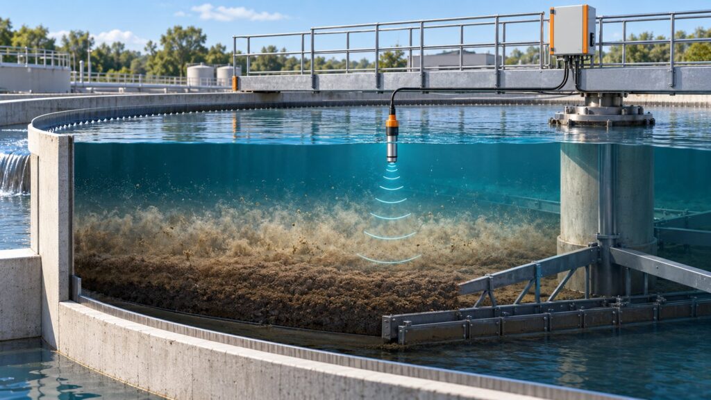
Clarifier sludge washout triggers effluent alarms. If you manage an industrial wastewater treatment plant, you already know this pain. In Indonesia, Permen LHK 80/2019 and PP 22/2021 govern environmental compliance. They mandate continuous SPARING outfall monitoring. They set rigid Total Suspended Solids (TSS) limits ranging from 30 to 100 mg/L based on your sector. When your secondary clarifier fails to contain its sludge, solids carryover hits the outfall. You instantly violate TSS limits. The Ministry steps in. You face administrative sanctions and PROPER downgrades. A continuous sludge blanket sensor fixes the root cause. It stops these outfall spikes. You manage the separation process before a compliance disaster wrecks your week.
The Pumping Dilemma: Washout Risks vs Dilute Sludge
Managing a secondary clarifier boils down to one engineering rule. Pump sludge, not water. Leave the sludge in the clarifier too long to thicken, and the bed rises. A sudden peak hydraulic load hits. Or nocturnal filamentous bulking occurs. The blanket pushes over the overflow weir. Over 70% of sudden TSS spikes at the effluent outfall stem from this exact washout mechanism.
The alternative is just as bad. Run the Waste Activated Sludge (WAS) and Return Activated Sludge (RAS) pumps continuously on a timer to stay safe. You end up pumping water. Dilute sludge destroys the efficiency of downstream thickeners and dewatering equipment. Your filter presses choke. Operators panic and increase polymer and coagulant dosing by 30% to 40% just to hit cake solid targets. You burn money.
Operators historically relied on manual Sludge Judge tools. Plunge a clear plastic tube into the clarifier twice a shift. Look at the mud line. It is a primitive system. Intermittent manual sampling ignores sudden process upsets. You cannot prevent a 3:00 AM washout with a reading taken at 4:00 PM the day before. The process demands continuous real-time depth tracking.
Underwater Pulse-Echo Sonar Physics
Modern plants deploy ultrasonic continuous level instruments. They abandon the plastic tubes. The technology tracks mud under meters of murky water using acoustic pulse-echo sonar.
A piezoelectric transducer sits 10 to 30 centimeters below the water surface. It fires high-frequency acoustic pulses straight down. The sound wave travels through the water. It hits boundaries where physical density changes. Specifically, the boundary between clear water and suspended solids.
This density shift alters the acoustic impedance ($Z = \rho \cdot c$). Here, $\rho$ is density and $c$ is the speed of sound. The impedance mismatch bounces the acoustic pulse back to the transducer. The instrument measures the Time-of-Flight (ToF) of the returning echo. It calculates the exact depth of the liquid-solid interface.
Temperature complicates this. The speed of sound in wastewater changes with heat. At 15°C, sound moves at 1450 m/s. It jumps +2.5 m/s for every degree Celsius increase. Industrial probes include an integrated temperature sensor to apply real-time thermal compensation. Distance calculations stay accurate despite diurnal temperature swings. A correct data logger channel scaling configuration pushes these compensated signals cleanly into your control room.
Frequency selection is a compromise. Low-frequency probes (130 to 160 kHz) suffer less acoustic attenuation. The signal penetrates up to 12 meters into heavy primary sludge beds. High-frequency probes (380 kHz to 1.1 MHz) work differently. They generate a narrow beam angle of 3° to 6°. They offer high spatial resolution. You need this resolution to detect the low-density “fluff layer” of secondary activated sludge.
Echo Profile Deconvolution
The ultrasonic pulse never bounces off a single hard surface. The clarifier remains a dynamic mess. The returning signal forms an echo envelope full of reflections. Controllers run an echo profile deconvolution algorithm to map four physical zones in the tank:
- Supernatant: The clear liquid zone at the top.
- Fluff Layer (Rag Layer): The volatile transition zone of light, uncompacted flocs (0.2% to 0.5% solids concentration or 2,000 to 5,000 mg/L).
- Consolidated Sludge Blanket: The dense bed of settled sludge ready for pumping (>1% to 3% solids).
- Tank Floor: The concrete or steel bottom.
Tracking the fluff layer changes everything. It operates as an early warning system. The fluff layer expands long before the heavy consolidated bed rises to dangerous heights. Tracking this specific transition zone stops light flocs from escaping the weir. This matters. Escaping flocs ruin turbidity vs TSS correlations at the final effluent channel.
Beating Scraper Arms and Biofouling
Putting sonar in an industrial clarifier means dropping it into a hostile mechanical environment. Rake arms sweep the tank floor. A metal arm passing under the acoustic beam triggers a massive false echo.
Controllers run an Abnormal Signal Filter (ASF) to reject this noise. The algorithm detects a sudden high-amplitude reflection that ignores the historical sludge profile. It identifies the scraper arm. It drops the false echo and holds the last known valid depth until the steel passes.
Surface scum skimmers break rigid probes. A rotating surface skimmer blade will snap a fixed transducer mount in half. You solve this with a pivot bracket. The blade approaches. The bracket swings up. The blade passes. Gravity drops the probe back into the water.
Biofouling remains a guarantee. Nutrient-rich active sludge coats the transducer face in slime and algae. This muffles the acoustic pulse. Probes require automatic cleaning mechanisms. You either run a motorized silicone wiper blade that sweeps the face, or a 6-bar pneumatic air-jet blast that scours the plastic clean.
| Feature / Technology | Ultrasonic Sonar Probe | Optical Profiler (Winch) | Manual Sludge Judge |
|---|---|---|---|
| Measurement Principle | Acoustic pulse-echo impedance | Mechanical lowering with IR sensor | Visual inspection via clear tube |
| Automation & Control | Continuous, real-time | Intermittent (winch cycles) | Manual, 1-2 times daily |
| Fluff Layer Detection | Excellent (with high frequency) | Good (measures exact profile) | Poor (depends on operator eye) |
| Scraper Interference | Handled via Echo Masking / ASF | High risk of cable entanglement | Only checked when safe |
| Maintenance Need | Low (auto wiper/air-jet) | High (cable wear, winch motor) | High labor overhead |
Automated RAS and WAS Pumping
A reliable sludge depth reading moves your clarifier from guesswork to automated pumping.
Tie the Return Activated Sludge (RAS) pumps to blanket depth. This maintains the biological inventory in the aeration basin. You keep the bed depth stable at 0.5 to 1.5 meters from the floor. You stop pulling too fast. The US EPA and WERF published data on this. Tuning RAS pumping with continuous blanket depth cuts pump energy use by 18%.
Compliance depends on the Waste Activated Sludge (WAS) pumps. You establish sensor alarm threshold configurations. You program a high-level pre-alarm. A Variable Frequency Drive (VFD) ramps up the WAS pump the second the fluff layer hits critical elevation. You pump the thickest possible sludge to the press. Polymer consumption drops by 30 to 40%. Sludge washouts become mathematically impossible.
Technical Limitations
Ultrasonic profiling has hard boundaries. Do not ignore them.
- No Replacement for Lab Tests: The sensor measures physical depth. It knows nothing about biological health. You still run laboratory Sludge Volume Index (SVI) and Mixed Liquor Suspended Solids (MLSS) tests.
- Frequencies Do Not Mix: You cannot run a single sonar frequency across all tanks. Primary clarifiers require different acoustics than secondary clarifiers.
- Air Bubbles Kill Sonar: Dense air bubbles scatter ultrasonic pulses. A sludge blanket sensor fails inside aerated bioreactors. Do not install it in an active dissolved air flotation (DAF) unit.
Telemetry Integration and SPARING Compliance
A standalone sensor has limited value. Wire the 4-20 mA or Modbus RTU output directly into an industrial GEOVOS 1000 Datalogger. The plant gains a real-time command center.
The GEOVOS unit plots the sludge profile trend on the dashboard. Operators see the upset hours before it happens. You program the datalogger’s logic controller to fire local relays. If the blanket spikes at 2:00 AM, the emergency sludge pumps kick on.
Telemetry bridges the gap between the clarifier and the final outfall. Control the sludge blanket aggressively. You eliminate the main cause of effluent TSS spikes. Sludge dewatering runs efficiently. Your SPARING monitoring system stays strictly compliant.
Share this article
Share this insight with your team.
Related Articles
Similar topics from the same category.

Monitoring station OPEX budget planning guide covering five cost pillars, cross-station comparison, hidden costs, and a modular worksheet for annual budgeting.

8 mandatory monitoring criteria for PROPER Blue rating under PermenLH 7/2025: SPARING, AQMS, B3, waste, peatland, mining, and SIMPEL audit.

Compare TDR and FDR soil moisture sensor principles, dielectric calibration limits for tropical peat, and multi-depth telemetry integration via GEOVOS 1000.