Tide Gauge Sensors: Non-Contact Radar vs. Hydrostatic Pressure vs. Bubbler for Ports and Coastal Monitoring
Comprehensive engineering guide to coastal and port tide gauge sensors: comparing non-contact radar, hydrostatic pressure transducers, and acoustic bubblers.
A ten-centimeter water level reading error at a marine jetty can ground a fully laden bulk carrier in the approach channel during spring low tide. That is not a theoretical hazard. IHO S-44 Edition 6 (2020) demands a Total Vertical Uncertainty (TVU) below 0.15 m for Special Order hydrographic surveys in port waters. Meeting that tight tolerance turns the choice of tide gauge sensor into a high-stakes engineering call, not a casual catalog pick.
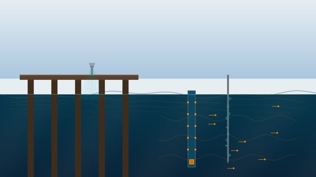
Three primary technologies compete for the job: non-contact microwave FMCW radar gauges, submerged hydrostatic pressure transducers, and gas-purged acoustic bubblers. Each faces distinct hazards in tropical marine environments. Barnacle biofouling, salinity-driven density shifts, and coastal squalls all degrade sensor reliability. A purpose-built maritime AWLR (Automatic Water Level Recorder) station engineered for these conditions underpins navigation safety, berth operations, and tidal flood mitigation.
Why Standard Ultrasonic and Hydrostatic Sensors Crash and Burn in Seawater
Drop an off-the-shelf freshwater ultrasonic sensor onto an ocean jetty. Your data will derail within hours. Ultrasonic sensors measure water level by bouncing acoustic pulses through the open air column above the surface. In open marine settings, that physics breaks down in three distinct ways.
First, steep vertical temperature gradients between the warm sea surface and cooler maritime breezes warp the speed of sound unpredictably. The resulting range errors resist software compensation. Second, coastal winds above 10 to 15 m/s deflect the acoustic cone off the perpendicular. The transducer receives false echoes or drops the signal entirely. Third, whitecap foam from breaking waves absorbs acoustic energy. The return signal simply dies.
Submerged hydrostatic pressure sensors dodge wind issues, but hit equally nasty traps. These instruments compute water elevation from the classic hydrostatic relation P = ρ·g·h, where ρ is water density. In freshwater rivers and lakes, density stays around 1,000 kg/m³. Clean and predictable. Seawater with salinity between 30 and 35 PSU pushes density to 1,020–1,030 kg/m³.
When transmitter firmware relies on a default freshwater density value, elevation readings drift by roughly 10 cm across a 10 m tidal range. That single calculation error blows past the IHO S-44 Special Order threshold.
Then comes tropical marine biofouling. Barnacles, green mussels, and macroalgae encrust submerged pressure diaphragms within three to six months. An encrusted diaphragm stops transmitting hydrostatic pressure cleanly. Readings drift off calibration. Cleaning requires commercial divers, piling on maintenance expense and safety risk at berths with heavy tidal currents.
Non-Contact Radar Level Meters: The Gold Standard for Coastal Tide Stations
Non-contact radar level meters broadcast FMCW (Frequency Modulated Continuous Wave) microwave signals at 26 GHz or 80 GHz. The antenna directs a focused microwave beam straight down. The reflection off the water surface yields distance via frequency shift, not acoustic transit time. Electromagnetic waves travel at the speed of light. They cut through air temperature gradients and coastal gales without budging.
The fundamental engineering win: zero submerged parts. The entire sensor assembly sits high and dry above the waterline on a cantilever mount or vertical standpipe. Nothing touches corrosive saltwater. Barnacles, mussels, and algae have nowhere to attach. Seawater density and salinity shifts have zero effect because microwave pulses bounce off the water surface without penetrating the liquid volume. System accuracy reaches ±2 mm (1σ), far exceeding the TVU requirements across every IHO survey order.
IOC/UNESCO published Manuals and Guides No. 14, Volume V: Radar Gauges (2016) specifically to document the global shift of tide stations toward radar. NOAA CO-OPS confirmed in Technical Report NOS CO-OPS 067 that the U.S. National Water Level Observation Network (NWLON) moved away from pneumatic bubblers to non-contact radar. The Radar Level Meter GRD-900 runs on this exact FMCW principle, feeding clean level data into port-side maritime AWLR installations.
Submerged Hydrostatic Pressure Sensors: Usable for Sheltered Berths, but Density Correction Is Mandatory
Hydrostatic pressure sensors still have a place in maritime monitoring. IOC/UNESCO Manual Vol. IV: An Update to 2006 confirms the ongoing utility of pressure transducers in sheltered shallow waters. Think enclosed docks, calm harbor basins, or narrow culverts where mounting an overhead radar antenna is structurally impossible. The catch: dynamic seawater density correction is non-negotiable.
The true water elevation formula for hydrostatic sensors in seawater requires rigour:
h_corrected = P_gauge / (ρ_seawater × g)
The parameter ρ_seawater is never a single static number. It varies with salinity (S), temperature (T), and pressure (P), calculated using the UNESCO EOS-80 equation of state or the modern TEOS-10 standard. In tropical Indonesian coastal waters, values swing between 30–35 PSU in salinity and 25–32°C in water temperature. At 30 PSU and 30°C, seawater density hovers around 1,020 kg/m³. At 35 PSU and 25°C, it climbs toward 1,025 kg/m³. Ignoring that variation injects systematic elevation errors that compound across every tidal cycle.
Correcting for density demands live salinity and temperature data, either from a co-located conductivity-temperature-depth (CTD) probe or from regular hydrographic field surveys. In Indonesia, SNI 7987:2014 from the Geospatial Information Agency (BIG) governs geodetic tidal control networks and mandates density-compensated records for marine stations. Our water level sensor selection guide details when site constraints justify hydrostatic gear over overhead radar.
Acoustic Bubbler Systems: Reliable Workhorses Burdened by Compressor Maintenance
Gas-purged bubblers measure water depth through straightforward pneumatics. Nitrogen gas or compressed air feeds down an orifice tube anchored near the seabed. The back-pressure required to force bubbles out of the nozzle equals the hydrostatic pressure of the water column overhead. A differential pressure sensor housed in a dry onshore shelter reads this back-pressure with high precision. Because the measurement electronics stay indoors, isolated from spray and swell, signal stability holds up well.
For decades, bubbler systems served as the baseline standard for NOAA CO-OPS and hydrographic agencies worldwide. The separation between the submerged orifice nozzle and dry onshore electronics proved durable.
Yet the mechanical drawbacks eventually forced a modernization wave. Compressors, desiccant dryers, and gas manifolds require constant maintenance, including filter swaps, lubrication checks, and cylinder replacements. The underwater orifice tube also catches heavy tropical biofouling. Mussels and barnacles choke the orifice mouth, altering bubble formation dynamics and creating drift that worsens over time.
NOAA CO-OPS documented that annual maintenance overhead for bubbler systems runs substantially higher than non-contact radar. That reality drove the NWLON modernization. In tropical port waters where sea temperatures hover between 28°C and 32°C, accelerated biofouling turns bubbler upkeep into an endless chore.
Engineering Decision Matrix: Radar vs. Hydrostatic vs. Bubbler
Building a port tide station requires balancing measurement physics against site maintenance access. A wave-damping stilling well with an orifice-to-pipe diameter ratio between 1:10 and 1:20 strips out high-frequency chop (3–15 second wind waves) so the gauge records pure astronomical tides. IHO S-44 Edition 6 establishes the benchmarks: Special Order under 0.15 m, Order 1a under 0.25 m, and Order 1b under 0.50 m. Our stilling well engineering guide covers pipe intake geometry in depth.
The table below contrasts all three tide gauge sensor architectures across key operational criteria:
| Parameter | Non-Contact FMCW Radar | Submerged Hydrostatic Pressure | Pneumatic Acoustic Bubbler |
|---|---|---|---|
| Measurement Principle | 26/80 GHz microwave surface reflection | Water column pressure on diaphragm (P = ρ·g·h) | Pneumatic back-pressure through submerged orifice |
| System Accuracy | ±2 mm (1σ) | ±5–10 mm (contingent on density correction) | ±3–5 mm (onshore differential cell) |
| Marine Biofouling Resistance | Immune (no submerged components) | Vulnerable (diaphragm fouled in 3–6 months) | Vulnerable (orifice nozzle choked by encrustation) |
| Density & Salinity Sensitivity | None (microwave ignores water density) | High (requires dynamic ρ_seawater calculation) | Moderate (back-pressure depends on liquid density) |
| Stilling Well Requirement | Recommended at exposed berths (1:10–1:20 ratio) | Optional (direct mounting or perforated tube) | Required (orifice anchored at pipe bottom) |
| IHO S-44 Special Order Compliance | Exceeds all TVU orders (±2 mm vs 150 mm limit) | Fails Special Order without live density tracking | Meets Special Order if calibrated regularly |
| O&M Overhead & Diver Support | Minimal (antenna wipe-down, zero divers) | Heavy (routine diver callouts for diaphragm cleaning) | Heavy (compressor checks, gas bottles, nozzle flushes) |
Field Deployment Strategy and Port Telemetry Integration
For modern coastal tide gauge stations at open ocean berths, bulk mineral terminals, oil and gas jetties, and hazard monitoring towers, non-contact radar is the clear engineering pick. Hydrostatic pressure sensors remain a sensible backup for covered docks and tight culverts where overhead brackets cannot fit, assuming dynamic density correction runs continuously. Bubblers belong strictly in legacy stations where pneumatic infrastructure already exists.
In real-world telemetry setups, the radar tide sensor connects via RS-485 Modbus RTU directly to a GEOVOS 1000 Datalogger. The logger samples sea level elevation at programmable intervals (typically every 1 to 6 minutes), buffers records on internal flash storage, and pushes packets over 4G cellular links to central servers. Tidal elevation streams straight to the port dispatch console, local Vessel Traffic Services (VTS), and regional storm surge monitoring feeds. High-water alarms trigger inside the logger firmware: when water level breaches critical astronomical thresholds, SMS and webhook alerts fire instantly to pilot stations and emergency response crews.
For coastal berths exposed to seasonal typhoons, pairing the tide station with an Argatech automatic weather station provides real-time wind speed, barometric pressure, and gust tracking to correlate storm surges with astronomical tides. Connecting every sensor into the GEOVOS 1000 via standard digital protocols (RS-485 Modbus RTU, SDI-12, or 4–20 mA) cuts down wiring runs and delivers bulletproof data availability in corrosive salt air.
Share this article
Share this insight with your team.
Related Articles
Similar topics from the same category.
Monitoring station OPEX budget planning guide covering five cost pillars, cross-station comparison, hidden costs, and a modular worksheet for annual budgeting.

8 mandatory monitoring criteria for PROPER Blue rating under PermenLH 7/2025: SPARING, AQMS, B3, waste, peatland, mining, and SIMPEL audit.

Compare TDR and FDR soil moisture sensor principles, dielectric calibration limits for tropical peat, and multi-depth telemetry integration via GEOVOS 1000.