Choosing Water Level Sensors: Radar, Ultrasonic, or Hydrostatic?
Compare radar, ultrasonic, and hydrostatic sensing by mounting, range, site conditions, maintenance, and data integration before specifying a system.
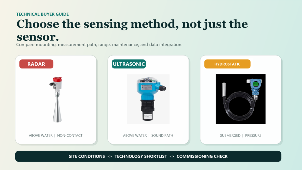
Choosing water level sensors starts with one practical question: can the instrument touch the water, and what lies between the mounting point and the surface? If the measurement must come from above without contact, radar and ultrasonic sensing belong on the initial shortlist. If a submerged instrument is acceptable and a reliable overhead mount is difficult to build, a hydrostatic transmitter may be the better direction.
That first rule is useful, but it is not a purchase specification. Vapor, foam, turbulence, sediment, changing water levels, maintenance access, and the required data output can all change the answer. The right technology is not automatically the one with the most impressive headline specification; it is the one that can produce dependable data in the actual installation.
Fortuna Argatech offers all three approaches and can connect them to an Automatic Water Level Recorder (AWLR). In a working monitoring system, sensor selection should be coordinated with the data logger, power supply, communications, dashboard, alarms, and field-verification process.
A quick framework for choosing water level sensors
Use this table to narrow the options before a site survey. It is a decision framework, not a substitute for a datasheet review, installation drawing, range calculation, and commissioning test.
| Technology | Sensor position | Main advantage | What to verify |
|---|---|---|---|
| Radar | Above the surface, non-contact | A strong candidate when non-contact measurement is required and the acoustic path may be challenging | Mounting geometry, objects in the beam, range, blind zone, and false reflections |
| Ultrasonic | Above the surface, non-contact | Practical where there is an open, stable sound path to the water | Foam, turbulence, vapor, temperature differences, obstructions, and blocking distance |
| Hydrostatic | Submerged in the water | Useful where overhead mounting is limited and stable submersion is feasible | Wetted materials, cable position, pressure range, drift, sediment, and calibration access |
The comparison separates the technologies into two broad families. Radar and ultrasonic sensors observe the surface from above. A hydrostatic transmitter measures the pressure of the water column from within the medium. That physical difference shapes installation work, exposure to interference, and the maintenance plan.
1. Start with mounting position and contact
Inspect the available structure before comparing model numbers. A bridge, tank roof, bracket, or beam above a channel can support a non-contact sensor. The mounting point still needs to be stable, reasonably accessible, protected from accidental movement, and aligned with a representative part of the water surface.
Where there is no dependable overhead structure, a hydrostatic sensor can reduce the need for an above-water bracket. The tradeoff is direct exposure: the sensor and cable remain in the medium. The design therefore needs to account for debris, sediment, impact, corrosion, changing cable position, and a safe cable route.
The contact decision also depends on the liquid. Wetted materials must be checked when water contains contaminants or when the medium is not simply clean water. In a river or open channel, shifting sediment and floating material can change the sensor’s local environment. Build a mounting sketch and document expected minimum and maximum water levels instead of selecting from a catalog image alone.
2. Examine the path between sensor and surface
For a sensor mounted above the water, the signal path matters as much as the instrument. Ultrasonic measurement relies on sound pulses and their returning echo. Endress+Hauser’s Prosonic T FMU30 technical information identifies blocking distance, obstructions, strong turbulence, foam, temperature differences, and high-vapor-pressure media as factors that should be considered.
This does not make ultrasonic sensing unreliable by definition. In water tanks, channels, and hydraulic structures with a suitable surface and a clear acoustic path, it can be a practical non-contact option. The important step is to avoid pointing the sensor at a wall, pipe, ladder, filling stream, or other object that can produce an unwanted echo.
Radar also measures from above, but it uses microwave signals. Fortuna Argatech’s Radar Level Meter page positions its 26 GHz configuration for non-contact measurement in conditions that may include vapor, foam, dust, or pressure. Mounting geometry still matters. The beam, nozzle or bracket, blind zone, and internal structures must be reviewed instead of assuming radar makes installation details irrelevant.
3. Match range and data needs, not headline accuracy alone
The measuring range must cover the lowest and highest expected levels while preserving the required clearance around the sensor’s operating limits. On a river, consider possible changes in bed elevation and mounting elevation. In a tank, include the nozzle, free space above the maximum level, and any unreadable zone close to the sensor.
Argatech publishes different configurations for the three product families. The Rika RKL-03 ultrasonic sensor is listed in 5, 10, 15, 20, and 30 meter variants, with published accuracy of 0.5-1 percent and 4-20 mA or RS485 output. The Radar Level Meter page lists a 0-30 meter range, +/-1-3 mm accuracy, and 4-20 mA plus RS485 Modbus output. These values come from separate product pages and should not be treated as a direct performance ranking without aligning the reference conditions, selected range, mounting arrangement, and measurement objective.
The Liquid Level Transmitter uses hydrostatic pressure and lists 4-20 mA or RS485 Modbus output, a typical 12-36 VDC supply, IP68 submersible construction, and several accuracy options. For this technology, the pressure range and installation depth need to cover the expected movement of the water surface.
Before requesting a quotation, define the resolution and time interval the operation actually needs. Flood alarms, tank inventory, well monitoring, and long-term operational trends do not necessarily require the same sampling rate or tolerance. A high-accuracy sensor cannot correct a moving bracket, a bad elevation reference, a logging interval that misses the event, or an unreliable communications link.
4. Include calibration and maintenance in the comparison
Non-contact sensors avoid direct immersion, but they are not maintenance-free. The transducer face, bracket, and signal path still need inspection. Dust, nests, condensation, changed alignment, or a new object in the beam can affect results. The design should provide a safe way to inspect the installation and compare the reading with a field reference.
Hydrostatic sensors have a different verification burden. The U.S. Geological Survey procedure for submersible pressure transducers notes that instruments can be affected by drift, offset, and suspension-system slippage. In its well and piezometer context, USGS recommends comparing transducer readings with direct water-level measurements and recalibrating periodically.
The practical lesson is broader than that specific procedure: define who checks the sensor, which reference they use, how often checks occur, and how corrections are documented. For hydrostatic installations, include the cable, vent tube where applicable, sediment position, and wetted-material compatibility. For every technology, make sure the logging interval is fast enough to capture the changes that matter to the operation.
5. Use a decision flow, then confirm it on site
The following flow can structure an early discussion between operations, engineering, and procurement.
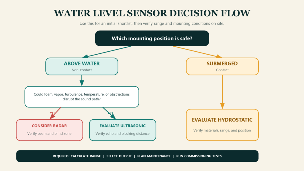
- Choose the possible sensor position. If the safe option is above the water, focus on radar or ultrasonic sensing. If submersion is acceptable and an overhead mount is impractical, evaluate hydrostatic sensing.
- Assess the measurement path. For non-contact options, document vapor, foam, turbulence, obstructions, temperature variation, maximum distance, and the required blind-zone clearance.
- Calculate the real range. Use expected minimum and maximum elevations, not only the normal operating depth.
- Select outputs and architecture. Match 4-20 mA or RS485 to the data logger, PLC, gateway, cable route, surge protection, and communications plan.
- Plan verification. Define reference checks, commissioning tests, inspection intervals, and the response to implausible or missing data.
This process normally produces a shortlist rather than an automatic final answer. One station may use radar, another ultrasonic, and a third hydrostatic sensing even when all three belong to the same monitoring program.
6. Evaluate the sensor as part of the monitoring system
A water-level value is useful only when it reaches the right user in a form that supports action. The specification should therefore cover the sensor, data logger or gateway, power, communications, server, dashboard, alarm logic, data retention, and maintenance access.
Fortuna Argatech’s AWLR can be configured around different sensor technologies to suit field conditions. This system perspective allows the team to discuss sensing and data integration together, including sampling intervals, trend displays, alarm thresholds, connectivity tests, and post-installation support. The final scope still needs to reflect the site and the user’s response procedure.
For a procurement document, ask the supplier to answer these questions in writing:
- Which sensing technology is recommended, and which site conditions support that recommendation?
- What is the effective measuring range after mounting geometry and blind zones are included?
- What are the main interference sources, and how does the design address them?
- Which output, protocol, power supply, protection, and cable length are included?
- How will elevation reference, calibration, and commissioning be completed?
- What routine checks are required, and how will anomalous data be identified?
- How will data be transmitted, stored, visualized, and converted into alarms?
- Which limitations must the operations team accept or manage?
Select with site evidence
A defensible choice can be explained with a mounting drawing, calculated range, medium conditions, integration plan, and verification procedure. If one of those elements remains unclear, the purchase decision is not ready.
Fortuna Argatech can help assess the measuring point, compare radar, ultrasonic, and hydrostatic options, and prepare an appropriate monitoring configuration. Bring the site layout, expected level range, mounting structure, water conditions, available power and network, required outputs, and alarm objective to the technical discussion.
Technical references
- Fortuna Argatech product pages for Radar Level Meter, Rika RKL-03, Liquid Level Transmitter, and Automatic Water Level Recorder, accessed July 23, 2026.
- Endress+Hauser, Technical Information: Prosonic T FMU30 – Ultrasonic Level Measurement, TI00440F/00/EN/15.14, 2014.
- U.S. Geological Survey, Groundwater Technical Procedures of the U.S. Geological Survey, Techniques and Methods 1-A1, 2011.
Share this article
Share this insight with your team.
Related Articles
Similar topics from the same category.
Poor weather station placement can cause 50% data bias. Learn the WMO-No. 8 and Indonesian BMKG siting standards for AWS sensors in industrial and mining sites.
Explore a technical engineering comparison between solid-state ultrasonic anemometers and mechanical cup-and-vane sensors for industrial weather stations.

Technical guide to conductivity sensors: comparing toroidal (inductive), 2-electrode, and 4-electrode contacting probes for industrial water and wastewater.