Stilling Well Design for River AWLR Stations: Mitigating Intake Lag and Dynamic Drawdown
Master AWLR stilling well hydraulic design. Learn to calculate USGS intake lag, mitigate Bernoulli drawdown, and design sediment sumps for tropical rivers.
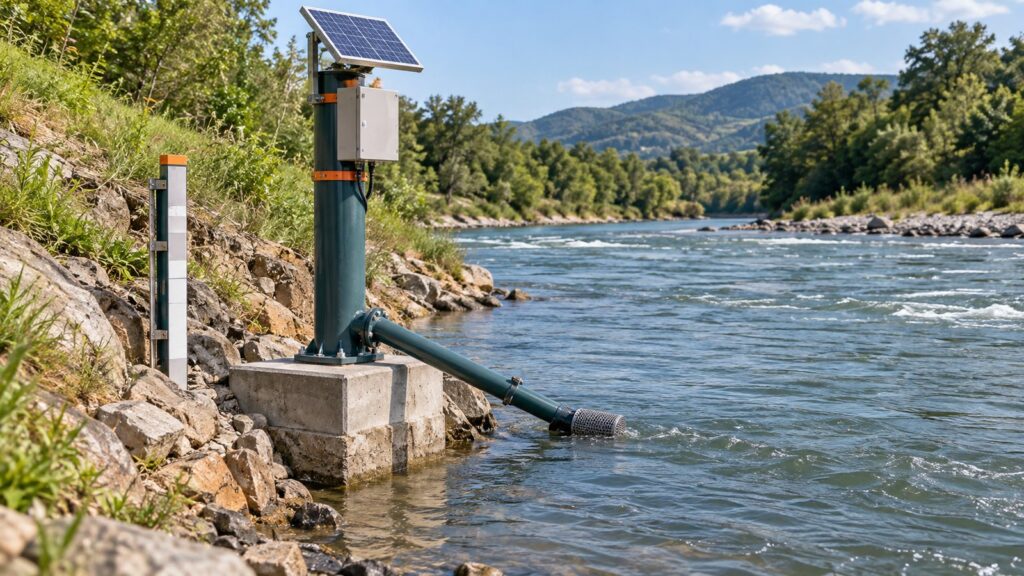
Hydraulic flaws in a stilling well wreck your data. During peak flow, the Bernoulli effect can suck the internal water level 10 to 30 cm below the actual river. Or worse, your well might suffer from intake lag, delaying the recording of critical flood waves. You cannot just guess the dimensions. A proper setup demands strict adherence to USGS TM 3-A7 parameters and ISO 4373:2022 ratios. We need to calculate intake pipe dimensions to prevent lag. We must also mitigate high-velocity drawdown using static tubes. Sediment sumps are non-negotiable for silt-heavy tropical rivers. Honestly, I have seen too many flooded stations fail because someone ignored these absolute basics. We will cover physical integration for hydrostatic, float, and radar sensors.
Why Stilling Wells Matter: Waves vs. Hydraulic Distortion
A stilling well basically does one job. It dampens surface waves and wind chop so the sensor can measure a stable mean water elevation. The well connects to the open river through horizontal intake pipes, which you must place below the lowest expected dry-season flow. This maintains hydrostatic equilibrium all year round. Float and hydrostatic sensors desperately need this damping. Otherwise, they just record high-frequency oscillation noise. That kind of garbage data will completely choke your telemetry system.
People focus too much on the physical casing. They bolt down a vertical pipe and completely forget the fluid dynamics. That is a rookie mistake. For an Automatic Water Level Recorder (AWLR) station, badly dimensioned intakes ruin your readings. Two extreme conditions cause the most pain in the field. First, intake lag delays the response to fast-rising floods. Second, dynamic drawdown artificially lowers the well water due to high-velocity crossflow. Both phenomena will destroy your hydrograph.
Sizing the Intake: Controlling Lag with USGS TM 3-A7
Intake lag happens when water cannot enter the well fast enough. Hydraulic friction chokes the flow. The USGS TM 3-A7 standard provides a strict formula for this lag ($\Delta h$):
$\Delta h = \frac{0.01}{g} \frac{L}{D} \left( \frac{A_w}{A_p} \frac{dh}{dt} \right)^2$
Look at the variables. Lag increases directly with pipe length ($L$). It gets exponentially worse with a smaller diameter ($D$). It scales with the square of the area ratio between the well and the pipe ($A_w/A_p$), and multiplies by the square of the stage change rate ($dh/dt$).
The USGS sets a hard limit. Maximum intake lag cannot exceed 0.1 feet (about 3 cm) during the worst realistic flood rise for your site. That is a tight margin. To kill waves without causing lag, ISO 4373:2022 suggests a 1:10 diameter ratio between the pipe and the well. That yields a 1:100 cross-sectional area ratio. In my experience, you should stick strictly to this baseline.
| AWLR Station Component | General Dimension / Standard Specifications |
|---|---|
| Compact Pipe Stilling Well | Diameter 300 to 600 mm (12 to 24 inches) |
| Walk-in Concrete Well | Diameter 1.2 to 1.8 meters |
| Intake Pipe (Compact Well) | Diameter 50 to 100 mm (2 to 4 inches) |
| Intake Pipe (Walk-in Well) | Diameter 100 to 150 mm (4 to 6 inches) |
| Plumbness Deviation | Maximum 1° vertical deviation |
Rivers with massive seasonal swings need more than one pipe. Tidal zones have the same problem. Standards like WMO-No. 168 demand multi-tier intakes at different elevations. This redundancy speeds up equalization. It also saves your data if mud buries the bottom pipe, which is critical for maintaining an accurate stage-discharge rating curve.
The Bernoulli Drawdown: High Velocity Suction
Fast water pulls hard. When streamflow crosses a flush intake pipe, it drops the static pressure. We call this dynamic drawdown. It literally sucks the water inside the well lower than the open river. The theoretical drawdown head ($\Delta h_d$) scales with the velocity head:
$\Delta h_d = C_d \frac{V^2}{2g}$
Flood velocities above 3 meters per second are brutal. The suction on a bare intake can depress your internal stage by 10 to 30 cm. That error ruins rating curves. You end up drastically underestimating peak flood discharges. I once saw a station report normal flow while the river topped its banks. Drawdown was the culprit.
You must modify the intake. Both USGS and ISO recommend static tubes. The simplest fix? A 90-degree pipe elbow pointing downstream. Just cap the end and drill static pressure holes on the sides. Alternatively, use flow-dampening baffles. A Twitchell or Ash baffle across the mouth works exceptionally well to deflect high-velocity flow lines. These physical structures create a stagnation zone, allowing the true hydrostatic pressure of the river to penetrate the well.
Silt Sumps and Maintenance in Tropical Rivers
Tropical rivers carry absolutely massive sediment loads. Our Indonesian monsoons turn rivers into flowing mud. You have to plan for sediment. If you build a well without a hopper bottom or a silt sump, you will fail. The intake will choke solid in just a month or two.
Follow the Indonesian National Standard (SNI 8062:2015) and USGS rules. You must drop the well bottom at least 0.3 to 0.6 meters below the lowest intake pipe invert. This dedicated clearance acts as your sediment trap. Sand, clay, and heavy gravel settle down there instead of plugging up the main hydraulic path.
A professional setup requires desilting features. Include a base cleanout plug for dry wells. Or better yet, install a flushing backwash system. You pump pressurized water to blast accumulated muck out through the intake pipe. Do not skip this. Nobody wants to dive into floodwaters or dismantle a steel structure just to clear mud.
Sensor Integration: Float, Hydrostatic, and Radar
Your physical layout dictates your water level sensor selection. You must adapt the interior to fit radar, ultrasonic, or hydrostatic tools:
- Float Encoder Sensors: A mechanical float needs space. The well diameter must fit the 20 to 30 cm float and its heavy counterweight. They must travel the full hydrograph without touching the walls. Keep plumbness deviation under 1 degree. Otherwise, cable friction destroys your accuracy.
- Submersible Hydrostatic Sensors: A Liquid Level Transmitter often sits in an internal perforated pipe. This shields the cable from turbulence and debris. Never drop the probe onto the floor. Suspend it 10 to 20 cm above the maximum expected silt line. If mud buries the diaphragm, the sensor becomes completely useless.
- Radar Waveguides: Sometimes the well acts as a waveguide for non-contact radar. The inner surface must be flawlessly smooth. PVC or steel works, but keep it free of weld seams or protruding bolts. Those cause false echoes. Drill ventilation holes near the top flange. Trapped air ruins the readings and causes terrible condensation.
Regardless of your sensor choice, the Fortuna Argatech GEOVOS 1000 Datalogger handles the integration. It accepts analog 4-20mA, SDI-12, or RS-485 Modbus RTU directly. Onboard digital spike filters guarantee stable, valid water level data before anything hits the telemetry network.
Field Standards and Staff Gauge QC
Engineering requires rules. In Indonesia, SNI 8062:2015 governs operational procedures. SNI 03-3414-1994 dictates site selection. These align perfectly with WMO-No. 168 and ISO 4373:2022.
Every single AWLR station requires an external manual staff gauge. This applies to high-end digital telemetry setups and legacy chart recorders alike. Install this visual scale out in the open river. Place it well outside the well’s hydraulic influence. You must tie it firmly to a static national geodetic benchmark.
Quality control means trusting nothing blindly. You must verify digital telemetry against the manual staff gauge. Do this during extreme low-flow periods and peak floods. If the sensor and the visual gauge drift apart by more than 3 cm in fast water, you have a major problem. That discrepancy flags severe hydraulic malfunction. It might be intake lag, mud blockage, or unmitigated Bernoulli drawdown. Fix the physical structure before you trust the data again.
Do not guess your specifications. Contact the Fortuna Argatech Engineering Consultation Team to discuss your exact station requirements. We ensure your stilling well design and turnkey telemetry integration deliver precise, reliable early warning data.
Share this article
Share this insight with your team.
Related Articles
Similar topics from the same category.

8 mandatory monitoring criteria for PROPER Blue rating under PermenLH 7/2025: SPARING, AQMS, B3, waste, peatland, mining, and SIMPEL audit.

Compare TDR and FDR soil moisture sensor principles, dielectric calibration limits for tropical peat, and multi-depth telemetry integration via GEOVOS 1000.

Permen LHK 14/2024 ties SPARING telemetry to daily administrative fines. Understand the formula, sensor risks, and edge validation defense.