Sensor Noise Filtering: Damping, Averaging, and When Filtering Masks a Problem
Learn about digital filter types for monitoring sensors, how to configure them in your data logger, and when to fix the noise source.
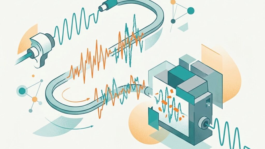
The dashboard shows random fluctuations. Field conditions are stable. The obvious move is enabling a filter in the data logger, and sensor noise filtering through digital processing will smooth out visible noise. But here’s the problem: an overly aggressive filter can bury a real event. A concentration spike, a sudden level change, a sensor failing quietly. This article covers what each filter type does, how to configure it, and when you should fix the noise source instead of stacking another filter on top.
What Signal Conditioning Does in a Monitoring System
Signal conditioning covers four functions: amplification, isolation, filtering, and linearization. Of these, filtering is the one field engineers touch most often.
Filtering happens at three points in the measurement chain. First, inside the transmitter. Sensors with 4-20 mA output often include an internal damping setting that smooths the analog signal before it reaches the data logger. Second, at the data logger itself: most loggers offer averaging, median filtering, or exponential smoothing on their input channels. Third, at the server or dashboard level, where post-acquisition processing runs after data has already been recorded.
The location matters. Transmitter-side damping alters the analog signal itself, so the data logger receives an already-smoothed signal. Data-logger-side filtering operates on samples that have already arrived. The logger can store raw values in parallel if it supports that capability, which is worth confirming before you commit to a configuration.
Common Filter Types and What They Do
Four filter types appear in most data loggers and transmitters:
Moving average sums N consecutive readings and divides by N. It cuts random noise amplitude by approximately √N. A 10-point average reduces random noise by roughly 3.2×. The trade-off: a larger window means slower response to real changes.
Exponential smoothing (IIR filter) weights recent readings more heavily, with older readings decaying exponentially. The smoothing factor controls how quickly past data fades from the output. You get continuous smoothing without needing a large data window, but it’s less effective than a moving average at suppressing high-frequency noise. In our experience, people tend to over-tune the smoothing factor when a simple moving average would do the job.
Median filter replaces each reading with the median of its N neighbors. It removes single-point spikes without shifting the signal baseline. An averaging filter, by contrast, pulls the mean toward the spike value. Use the median filter when you see occasional sharp outliers but a steady underlying signal.
Damping time constant is a parameter common in 4-20 mA transmitters. A higher damping value yields a smoother output but slower step response. In Rosemount pressure transmitters, for example, the damping constant dictates how fast the mA output tracks an actual pressure change.
How Damping Affects 4-20 mA and RS-485 Sensor Output
The difference between 4-20 mA and RS-485 output affects where filtering takes place.
With 4-20 mA sensors, damping happens inside the transmitter and modifies the analog signal itself. The data logger receives a pre-filtered signal. There is no option to read the raw value once damping is enabled. Set the damping too high and the logger records readings that lag behind actual conditions. We’ve seen sites where a 10-second damping constant on a pressure transmitter masked a valve chattering at 2 Hz, so the operator never knew about it until the valve failed.
With RS-485/Modbus sensors, some devices provide both raw and filtered values in separate Modbus registers. This gives you flexibility: the data logger can read the filtered value for the dashboard display while storing the raw value for analysis. Not all sensors offer this. Check the sensor’s register map before assuming it’s available.
Choosing a Filter Setting: Noise Type, Response Need, and Alarm Impact
Filter selection is not about cranking up the highest available setting. You need to evaluate several factors together:
Identify the noise type. Random noise (small, patternless fluctuations) responds well to a moving average. Isolated sharp spikes from momentary electromagnetic interference are better handled by a median filter. Periodic noise with a repeating pattern? That needs source investigation, not just filtering. Don’t mask a 50 Hz pickup with a heavier average.
Determine the acceptable response delay. Multiply the number of samples in the filter window by the data logger scan interval. That gives you the effective filtering time. A 10-sample moving average at a 1-second scan interval means 10 seconds of delay. For parameters that demand fast response, like water level at a flood-warning station, that delay is probably unacceptable.
Check alarm threshold interaction. An aggressive filter can delay the output’s crossing of an alarm threshold, so the alarm may trigger after the actual event has already occurred or resolved. Make sure your filter delay doesn’t exceed the expected response time of your alarm system.
Consider the logging interval. If your scan rate is already slow (say, once per minute), adding a 10-point average means you’re smoothing over 10 minutes of data. That’s a long time to hide a transient event.

When Filtering Is the Wrong Answer
Filtering reduces visible noise. It does not fix the source. Some conditions require physical correction, not filter configuration:
Grounding faults. Ground loops and poor grounding produce systematic noise that no digital filter will eliminate. You need to address grounding and EMI mitigation at the monitoring station at the physical layer before touching any filter setting.
Cable problems. A broken shield or corroded connector creates intermittent noise. Fix the cable. Proper sensor cable selection and installation solves this, not more damping.
Sensor degradation. If a previously stable sensor suddenly becomes noisy, the cause is likely physical: fouling, membrane aging, sensing element damage. Filtering a degrading sensor produces readings that look smooth on the dashboard but no longer represent the measured parameter. I’d argue this is the most dangerous scenario, because the data looks fine until someone pulls the sensor and finds it’s half-fouled.
EMI sources. Electromagnetic interference from variable-frequency drives, motors, or switching equipment requires physical mitigation: shielding, cable rerouting, ferrite chokes, or analog EMI filters.
The bottom line: if noise appears suddenly on a sensor that was previously stable, investigate the physical cause first. Digital filtering applied over a physical fault produces clean-looking but unreliable data and can generate misleading data quality flags.
When to Involve a System Integrator
Configuring a filter on a single sensor with one data logger is simple enough for a field technician. But some situations call for system-integrator involvement.
Multi-sensor stations with mixed protocols need careful attention. A combination of 4-20 mA and RS-485 channels on the same data logger requires per-channel filter configuration matched to each sensor’s characteristics. Installations subject to regulatory data requirements, such as SPARING compliance monitoring stations, need verification that filtering doesn’t compromise data acquisition standards. High-accuracy applications require validation that the filter introduces no systematic bias.
Fortuna Argatech configures signal conditioning parameters during system integration across all product lines, from the GEOVOS 1000 Datalogger to AQMS and weather stations. If filter configuration at your monitoring station needs evaluation, contact our technical team.
Share this article
Share this insight with your team.
Related Articles
Similar topics from the same category.
Poor weather station placement can cause 50% data bias. Learn the WMO-No. 8 and Indonesian BMKG siting standards for AWS sensors in industrial and mining sites.
Explore a technical engineering comparison between solid-state ultrasonic anemometers and mechanical cup-and-vane sensors for industrial weather stations.

Technical guide to conductivity sensors: comparing toroidal (inductive), 2-electrode, and 4-electrode contacting probes for industrial water and wastewater.