Parshall Flume Submergence Ratio: How to Correct Submerged Flow in SPARING
An operational guide to diagnosing submerged flow in Parshall flumes, applying hydraulic corrections, and automating dual sensors in SPARING dataloggers.
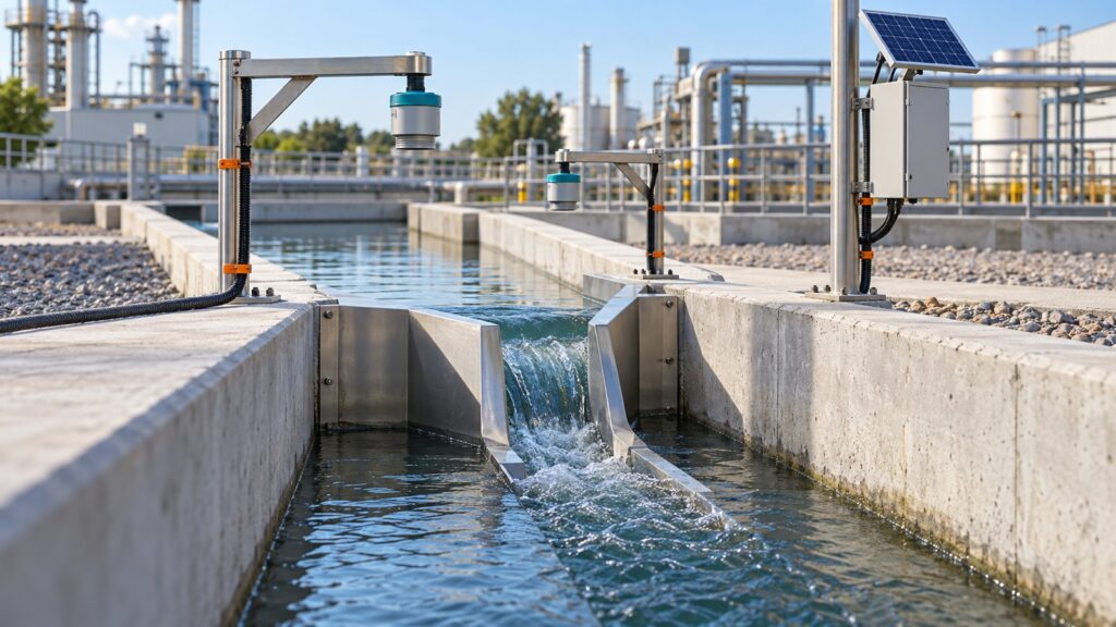
Wastewater effluent readings often spike violently during a heavy storm or a high tide. The immediate reaction is to blame the sensor calibration. Usually, the sensor is fine; the flume itself is drowning. Submerged flow in a Parshall flume happens when backwater from the receiving river or estuary backs up into the measuring channel. The Indonesian Ministry of Environment and Forestry (KLHK) enforces a strict $\pm 10%$ accuracy tolerance for SPARING flow measurement. That tolerance means nothing if the datalogger is running the wrong math on a flooded flume.
This is a serious compliance risk. The daily flow rate is the primary multiplier for calculating the daily Water Pollution Load ($kg/\text{day}$). If hydrostatic pressure tricks the sensor into reading a massive flow surge when the water is actually just pooling, the pollution load sent to the ministry’s server inflates instantly. Companies get hit with administrative sanctions and PROPER downgrades over artificial data. To protect your SPARING Data Completeness track record, you have to diagnose submergence and correct it using a dual-sensor setup.
Hydraulic Anatomy: Free Flow vs. Submerged Flow in Parshall Flumes
Open channel flow measurement relies entirely on gravity and a predictable drop in energy. A Parshall flume narrows at the walls and drops at the floor to force the water to accelerate. This creates critical depth at the throat. That critical depth forces a hydraulic jump, which acts as a physical wall, isolating the upstream measuring section from whatever the downstream water is doing.
As long as the water falls freely (free-flow), the math is incredibly simple. You only need one upstream head measurement ($H_a$), taken two-thirds of the way up the converging section. The empirical equation is just $Q = C \cdot H_a^n$. Almost every basic flow meter relies on this single-sensor logic.
But physics changes when the receiving river rises. When tailwater backs up, it drowns the hydraulic jump. This is submerged flow. The backwater acts as a dam, slowing the physical discharge while simultaneously raising the upstream water level. The single $H_a$ sensor reads that rising water and calculates a massive flow surge, completely blind to the fact that the actual water velocity has dropped to a crawl.
Calculating Submergence Ratio ($S$) and Transition Thresholds ($S_t$)
You cannot fix submergence by guessing. You have to calculate the exact submergence ratio ($S = H_b / H_a$). It is simply the water depth at the throat ($H_b$) divided by the upstream depth ($H_a$).
This math demands perfect sensor alignment. Both the $H_a$ and $H_b$ sensors must be zeroed to the exact same elevation: the flat floor of the converging section (the crest datum). The $H_b$ sensor sits right inside the throat, just before the diverging section begins.
Not all flumes drown equally. The submergence transition threshold ($S_t$) is the exact ratio where backwater chokes the flow enough to cause a 1% error in the free-flow calculation. A wider throat handles backwater better than a narrow one.
ASTM D1941 and the USBR lay out the exact limits. Tiny 1–3 inch flumes drown at 50%. Standard 1–8 foot flumes hold out until 70%. Massive municipal flumes over 10 feet can withstand 80% submergence before the data breaks.
| Flume Size (Throat Width) | Transition Threshold ($S_t$) | Submergence Ratio Percentage |
|---|---|---|
| 1, 2, and 3 inches | $0.50$ | 50% |
| 6 and 9 inches | $0.60$ | 60% |
| 1 to 8 feet | $0.70$ | 70% |
| 10 to 50 feet | $0.80$ | 80% |
Knowing these limits lets environmental engineers dial in the SPARING Sensor Response Time $T_{90}$. If you know exactly when the flume transitions, you can stop the datalogger from reporting garbage data.
Calculation Methods and Submerged Flow Correction Formulas (ASTM D1941 & USBR)
Running the standard free-flow equation on a submerged flume is a regulatory disaster. The datalogger will over-read the true physical flow by 10% to 50%. Coastal plants dealing with tidal lock face this daily. They end up reporting massive, fabricated pollution loads simply because they are using the wrong formula.
You don’t have to tear out the concrete to fix this. For standard 1-to-8-foot flumes, ASTM D1941 provides a clean mathematical fix: $Q_{submerged} = Q_{free} – Q_{correction}$. You calculate what the free flow would be, and then subtract a correction factor based on the flume’s size multiplier ($M$) and a base table value ($C$). It is basic algebra that saves companies from compliance fines.
Small 1-to-3-inch flumes skip the subtraction. They use direct polynomial calibration curves to map the relationship between $H_a$, the submergence ratio, and the actual flow.
But math has a hard ceiling. The USBR explicitly states that once a Parshall flume hits 90% submergence, no formula can save it. At 90%, the water surface is practically flat. If a sensor misreads the depth by just 1 millimeter, the final flow calculation swings by tens of percent. At that point, the flume is a pipe, not a measuring device.
Dual-Sensor Telemetry Architecture and Datalogger Automation
Nobody has the time to sit at a control panel doing long division during a rainstorm. If a flume is prone to flooding, the instrumentation has to react automatically. That means running a dual-sensor setup: one ultrasonic sensor at $H_a$, and a second one at $H_b$.
Non-contact sensors like the Rika RKL-03 are the standard here. Hanging an ultrasonic or radar unit above the flow keeps it out of the sludge. Submersible pressure probes die quickly in raw wastewater; they get covered in biofilm or crushed by debris.
Both sensor signals feed straight into an edge datalogger. Modern industrial units like the GEOVOS 1000 handle the math natively. You set up a virtual channel to constantly divide $H_b$ by $H_a$. The moment that ratio crosses the ASTM threshold, the logger instantly swaps from the free-flow equation to the submerged-flow correction. It pushes the clean, corrected data straight to the Fortuna Argatech SPARING server, locking out any chance of over-reporting.
When Numerical Correction is No Longer Enough: Civil and Hydraulic Engineering Solutions
Code cannot fix terrible civil engineering. If a flume lives perpetually above 90% submergence, the math is dead. You have a structural problem.
When the flume is totally drowned, you have to break concrete. The floor has to be raised to restore the hydraulic drop, or the open channel has to be scrapped entirely for an inline acoustic Doppler or magnetic flowmeter. Gravity flow requires a gradient. You cannot negotiate with physics.
And sensors cannot fix neglected plumbing. The $H_b$ measurement usually relies on a small pipe feeding a stilling well. If that pipe fills with sludge, the $H_b$ sensor reads a static puddle while the main channel floods. The datalogger blindly runs the math on a dead sensor, spits out corrupted data, and fails the next KLHK performance audit. If you want the telemetry to handle the math during a flood, you have to keep the stilling wells clean.
Share this article
Share this insight with your team.
Related Articles
Similar topics from the same category.

Monitoring station OPEX budget planning guide covering five cost pillars, cross-station comparison, hidden costs, and a modular worksheet for annual budgeting.

8 mandatory monitoring criteria for PROPER Blue rating under PermenLH 7/2025: SPARING, AQMS, B3, waste, peatland, mining, and SIMPEL audit.

Compare TDR and FDR soil moisture sensor principles, dielectric calibration limits for tropical peat, and multi-depth telemetry integration via GEOVOS 1000.