When Should You Clean a Water Quality Sensor?
Recognize water quality sensor fouling, separate cleaning issues from calibration drift, and set maintenance intervals from site conditions and data risk.
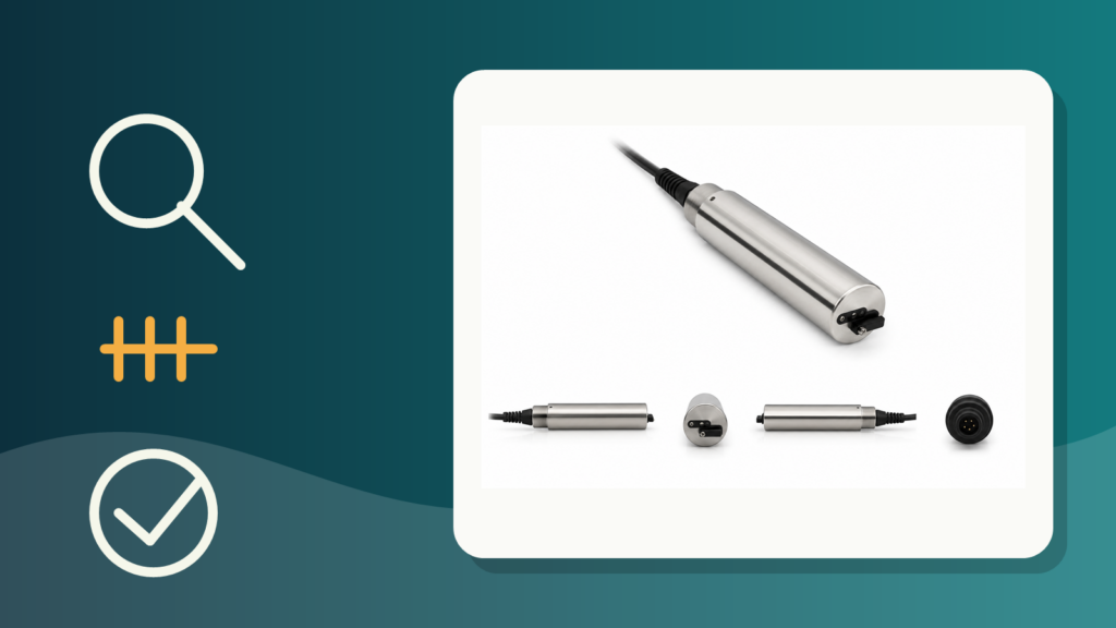
Water quality sensor maintenance should not follow the same calendar at every site. Record the condition and reading before cleaning, then use the post-cleaning result and calibration check to determine whether the problem is fouling, drift, or an equipment fault.
The order matters. Cleaning a probe before capturing the initial evidence removes the clearest clue about how much the sensing surface affected the data.
Water quality sensor maintenance starts with three different faults
A slow, unstable, or unexpected reading does not automatically mean that the sensor needs calibration. Three conditions lead to different actions.
| Condition under review | Main clue | Next check | Possible action |
|---|---|---|---|
| Fouling on the sensing surface or measurement area | The reading changes after deposits or biological growth are removed | Compare readings before and after cleaning under sufficiently stable conditions | Change the cleaning method or interval |
| Calibration drift | A clean sensor still deviates when checked with an approved standard or procedure | Run the model-specific calibration check | Recalibrate if the procedure and acceptance criteria allow it |
| Sensor or system fault | The sensor cannot be calibrated, does not agree with a verified reference, or remains abnormal after checks | Verify the reference, wiring, power, transmitter, configuration, and physical condition | Service it, take it out of use, or install a prepared backup unit |
The USGS procedure separates fouling error from calibration drift by recording readings before cleaning, after cleaning, and in calibration standards. This distinction is practical: cleaning restores contact between the sensor and the medium, while a calibration check evaluates the instrument response against a known reference.
Set the interval from data risk, not a generic calendar
The USGS continuous water-quality monitor guidance states that maintenance frequency is governed by fouling rate and varies with sensor type, hydrologic and environmental conditions, and season. A rule such as “clean every month” therefore needs site evidence before it can be treated as a suitable interval.
An initial interval should account for:
- the parameter and construction of the sensing surface;
- sediment, suspended solids, oil, mineral deposits, algae, or organisms reaching the probe;
- mounting position, flow, depth, a flow cell, or sample tubing;
- seasonal and media-temperature changes;
- the consequence of biased or missing data;
- access time, field safety, reference equipment, and backup availability;
- a wiper, brush, or other cleaning mechanism on the installed model.
Within its monitoring program, the USGS notes that dissolved oxygen, pH, and turbidity sensors tend to be more affected by fouling than temperature and specific-conductance sensors. That is not a universal ranking for every process and product. It shows why one probe’s schedule should not be copied to another without evidence.
Take the before-cleaning reading first
Traceability starts before the probe is removed. Record the time, site condition, primary-system value, device status, and a verified field-reference reading when the project procedure provides one. A photograph of visible deposits can also help when site policy permits it.
Inspect for chemical precipitates, stains, siltation, biological growth, physical damage, and mounting problems. Clean the sensor according to the exact model manual, return it to a representative measurement point, allow it to stabilize under the approved procedure, and capture the new reading.
The difference between the pre-cleaning and post-cleaning readings can indicate fouling when the medium remains sufficiently stable during the work. If flow, process conditions, or water quality change quickly, that comparison requires caution. Closely aligned timestamps and a field reference help distinguish an environmental change from a sensor change.
A sequence that preserves the evidence
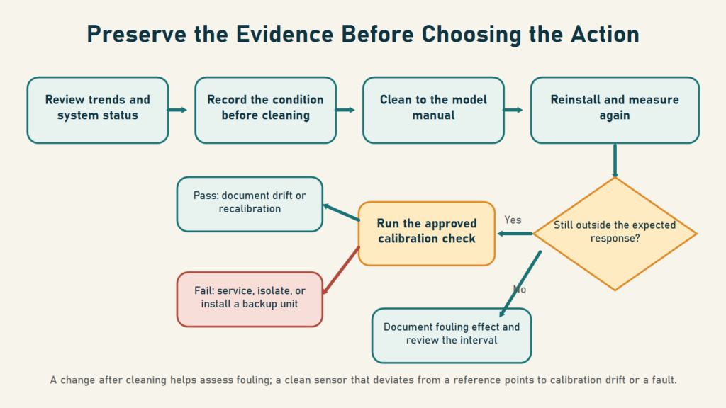
Use the following sequence as a framework, then adapt it to the device manual, safety procedure, and project quality plan.
- Review the data and system status. Check trends, diagnostic alarms, data gaps, power, communications, and recorded process changes at the same time.
- Capture the condition before cleaning. Record the sensor value, reference reading, timestamp, mounting condition, and visible fouling.
- Clean according to the model manual. Use only the tools, materials, pressure, and contact time permitted for that sensor.
- Reinstall and measure again. Allow stabilization, then compare the cleaned reading with the initial data and the reference.
- Run the calibration check. If the clean sensor still deviates, follow the approved standards, temperature controls, sequence, and acceptance criteria.
- Assign the sensor status. A sensor that cannot be calibrated or remains inconsistent after the reference is verified should be serviced, removed temporarily, or replaced with a calibrated backup.
This order avoids two shortcuts: erasing fouling evidence by cleaning too soon, and changing calibration coefficients to hide a contaminated sensing surface.
Why a universal cleaning recipe is unsafe
The cleaning method depends on the deposit and sensor construction. The Endress+Hauser pH/ORP manual reviewed for this article, for example, specifies different treatments for oily films, mineral deposits, sulfides, proteins, and biological buildup. It also includes chemical-hazard warnings and calls for thorough rinsing and recalibration after cleaning.
That model-family procedure is not a recipe for every probe. A pH electrode, dissolved-oxygen membrane, turbidity or TSS optical window, conductivity cell, and UV sensor can use different materials, seals, coatings, and mechanical limits. A treatment accepted for one model may damage another or create an exposure risk for the technician.
Use the correct model and manual revision. Confirm the safety data sheet, protective equipment, disposal method, and site work permit as applicable. The Argatech guide to pH sensor troubleshooting provides related diagnostic context, but the installed-unit manual still governs field work.
Wipers reduce work but do not remove inspection
Wiper and shutter mechanisms can reduce fouling under some conditions. The USGS reports lower fouling in some turbidity-instrument deployments that used those mechanisms. Fortuna Argatech’s current TSS sensor page also lists an automatic cleaning brush for the optical window.
The mechanism does not clean the entire installation. Deposits can remain on the housing, mounting hardware, flow cell, sample tubing, cable, or surrounding flow path. The brush itself also needs inspection for obstruction and damage. Automatic cleaning is therefore one fouling control, not a substitute for inspection, verification, and service.
For an ONLIMO system, the parameter set depends on the sensor configuration and site requirement. The maintenance plan should follow the architecture that is actually installed: sensors, datalogger or gateway, power, communications, dashboard, and the response procedure used when data cannot be trusted.
Turn maintenance logs into usable monitoring data
A work note that only says “sensor cleaned” cannot explain the resulting data change. A traceable log should capture:
- start and finish time, monitoring point, and model or asset identifier;
- sensor and site condition before cleaning;
- readings before and after cleaning, including units;
- the reference instrument or standard and its verification status;
- the cleaning method and manual reference;
- calibration-check results and any coefficient change;
- damage, parts, sensor replacement, or backup-unit use;
- the decision applied to data from the affected interval;
- the next inspection date and the reason for that interval.
When the platform supports it, a maintenance event can be marked on the dashboard so that a step change is not interpreted without context. This is a system-design recommendation, not a feature that should be assumed to exist in every project.
Treat the first interval as a testable assumption
Start with a conservative interval that reflects data risk, site access, the device manual, and genuinely documented experience. After several cycles, compare visible fouling, pre- and post-cleaning changes, calibration results, lost data, and field workload. Lengthen or shorten the interval from that record.
Fortuna Argatech can help review measurement points, sensor configuration, data integration, backup requirements, and maintenance-log fields for water-quality monitoring systems. Prepare the sensor list, manuals, permitted installation photos, example trends, calibration history, media conditions, and data-quality objective before discussing the maintenance plan with the Fortuna Argatech team.
Sources used
- Wagner, R.J., Boulger, R.W., Jr., Oblinger, C.J., and Smith, B.A. Guidelines and Standard Procedures for Continuous Water-Quality Monitors: Station Operation, Record Computation, and Data Reporting. U.S. Geological Survey Techniques and Methods 1-D3, 2006.
- Endress+Hauser. Operating Instructions: pH/ORP Sensors and Reference Half Cells, document family BA01572C, reviewed through the Indonesian edition dated 27 April 2020.
- U.S. Environmental Protection Agency. Water Sensors Toolbox, updated 15 January 2026.
Share this article
Share this insight with your team.
Related Articles
Similar topics from the same category.

Poor weather station placement can cause 50% data bias. Learn the WMO-No. 8 and Indonesian BMKG siting standards for AWS sensors in industrial and mining sites.

Explore a technical engineering comparison between solid-state ultrasonic anemometers and mechanical cup-and-vane sensors for industrial weather stations.

Technical guide to conductivity sensors: comparing toroidal (inductive), 2-electrode, and 4-electrode contacting probes for industrial water and wastewater.