Ultrasonic vs Cup-and-Vane Anemometers: Choosing the Right Wind Sensor for Industrial and Mining Stations
Explore a technical engineering comparison between solid-state ultrasonic anemometers and mechanical cup-and-vane sensors for industrial weather stations.
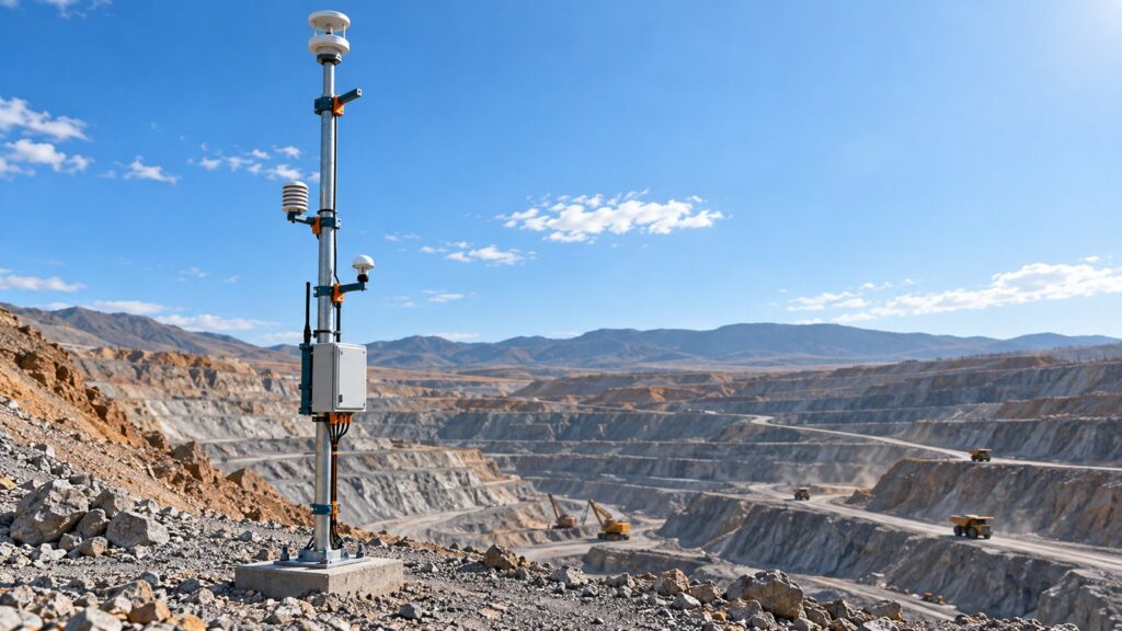
When a wind sensor dies at the top of a 10-meter mast, maintenance budgets bleed. Especially in harsh industrial environments. At first glance, mechanical cup-and-vane sensors look like the smart, cheap option. You bolt them up and they spin. But open-pit mines produce abrasive dust. Ports blast equipment with maritime salt. That environment chews through mechanical bearings in months. Once the bearings degrade, the sensor needs a much stronger wind just to start spinning, and it spits out wildly inaccurate data the second a heavy gust hits.
Solid-state ultrasonic anemometers solve the moving-parts problem completely. They offer instant response rates and rarely need maintenance. But they come with their own baggage. They eat more electrical power and can go completely blind during heavy rain if you do not account for acoustic attenuation. We need to look at how both of these sensors actually work in the real world. Let’s break down the physics, look at the dynamic errors, and figure out which anemometer actually belongs on your weather station tower.
The Physics of Wind Measurement
Every meteorological instrument reacts to air movement differently. The underlying physics strictly dictate what the sensor can and cannot do in the field.
Aerodynamic Drag in Cup-and-Vane Sensors
Mechanical sensors spin because of aerodynamic drag. It is that simple. The concave face of the cup catches the wind and creates high drag ($C_d \approx 1.4$). The convex trailing face produces much lower drag ($C_d \approx 0.4$). That pressure difference generates torque. The rotor spins.
Right below that spinning cup, a potentiometer or an optical encoder tracks the mechanical tail vane to log wind direction. Manufacturers calibrate these instruments in perfectly controlled wind tunnels, mapping rotational frequency against actual wind speed following ASTM D5096 and ISO 17713-1 standards.
Acoustic Transit-Time Differential
Ultrasonic anemometers scrap the mechanical approach entirely. A standard 2D sensor measures wind by firing acoustic wave pulses back and forth between fixed piezoelectric transducers. The distance ($L$) between them never changes.
If you read the ISO 16622:2002 testing standards, the physics are brilliant. An acoustic wave traveling with the wind ($t_1$) reaches the other side faster than a wave fighting against the wind ($t_2$). The sensor calculates the wind velocity ($v$) using the differential equation of those reciprocal transit times:
$v = \frac{L}{2} \left(\frac{1}{t_1} – \frac{1}{t_2}\right)$
That specific math cancels out the speed of sound ($c$) entirely. The result? Massive atmospheric temperature swings and humidity drops won’t distort your wind speed readings.
Dynamic Error Analysis and Mechanical Inertia
Wind tunnels are controlled and sterile. Real atmospheric wind is violent, turbulent, and unpredictable.
The Overspeeding Phenomenon
Wind does not blow at a static speed. It hits in gusts. This is a massive problem for any device that relies on physical mass to move. Engineers measure a mechanical sensor’s dynamic response using a distance constant ($L$). This is the length of the air column required for the rotor to react to 63.2% of a sudden wind speed change. Usually, it sits between 2 to 5 meters.
The WMO-No. 8 guidelines and classic aerodynamic research (Busch & Kristensen 1976) point out a fatal flaw here. Cup anemometers react asymmetrically. The heavy rotor spins up very quickly when a gust hits. But when the wind drops, momentum keeps the heavy cups spinning. They decelerate too slowly. Because of this inertia, mechanical sensors suffer from dynamic overspeeding. They artificially inflate reported wind speeds by +3% to +12% in highly turbulent areas.
Ultrasonic devices process acoustic signals at 10 to 50 Hz. Zero moving parts means zero mass. They instantly capture the exact peak profile of a wind gust without any inertia lag.
Low Wind Detection Limits and Bearing Wear
Industrial hydrometeorological monitoring isn’t just about surviving typhoons. If you run a massive mining operation under Indonesian Kepmen ESDM No. 1827 K/30/MEM/2018 regulations, accurately logging perfectly calm hours is legally required.
Your local microclimate data feeds directly into industrial air quality monitoring systems (AQMS). The software needs that data to model exactly where toxic dust or invisible gases will settle. In modeling software like AERMOD, wind velocities dropping under 1 m/s cause dangerous localized pollution buildup.
Starting Threshold Degradation
A brand-new cup anemometer needs a starting push of about 0.3 to 0.8 m/s just to overcome the static friction in its ball bearings. But put that sensor near the ocean, or in an open-pit mine. Salt crystallization and abrasive silica dust will shred those tiny bearings.
Over 6 to 12 months, that friction compounds. The starting threshold quietly creeps past 1.5 m/s. Your dashboard reports zero wind, but the air outside is actually moving at 1.2 m/s. That silent failure destroys the validity of your expensive air dispersion models. Ultrasonic sensors keep their starting threshold locked at an absolute 0.01 m/s. Nothing degrades because nothing rubs together.
Practical Limitations of Ultrasonic Sensors
Solid-state sensors are not magic. They have their own physical vulnerabilities, and your overall station integration has to account for them.
Extreme Tropical Rainfall Attenuation
According to WMO-No. 8 and ISO 16622, heavy tropical rainfall over 50 mm/hour creates a physical wall. Dense rain or water pooling on the transducer faces scatters the ultrasonic waves. The sensor drops data or throws an invalid signal warning flag. If you deploy these in the tropics, you must buy models engineered with aggressive water-shedding geometries.
Electrical Power Budget
Mechanical reed switch sensors pull virtually zero power. You barely have to factor them into your solar panel sizing calculations for off-grid remote stations. Ultrasonic modules are entirely different beasts. Their digital signal processors (DSP) pull a continuous 5 to 50 mA. That is 60 mW to 600 mW running 24/7. During an overcast monsoon season, that relentless active power draw will gut your battery autonomy if you didn’t size the solar array correctly.
External Acoustic Cavity Interference
The gap between the acoustic transducers is wide open to the environment. Spiders love to build webs there. Birds treat it as a toilet. Even a minor physical blockage on the transducer will blind the acoustic transit calculations. Installing professional bird spikes is absolutely mandatory during your site survey execution phase. Do not skip it.
Engineering Comparison Matrix: Ultrasonic vs Mechanical
Here is the brutal head-to-head comparison for your procurement team.
| Performance Parameter | Ultrasonic (Solid-State) | Cup-and-Vane (Mechanical) |
|---|---|---|
| Fundamental Principle | Differential acoustic transit time | Aerodynamic inertia drag |
| Starting Threshold | $\approx$ 0.01 m/s (Extremely low) | 0.3 – 0.8 m/s (Degrades >1.5 m/s over time) |
| Moving Parts Wear | Zero physical mechanical wear | High (Bearings destroyed by dust and salt) |
| Dynamic Gust Error | Instantaneous profile capture | Systematic overspeeding bias (+3% to +12%) |
| Active Power Draw | High (60 – 600 mW continuous) | Extremely Low ($\approx$ 0 mW, passive pulsing) |
| Weather Vulnerability | Signal scatters in extreme rain >50 mm/h | Rain resistant, but freezes solid in ice |
| Maintenance Interval | $\approx$ 3 – 5 Years | $\approx$ 12 – 18 Months (Requires bearing swaps) |
| Initial Capital Expense | Relatively High | Low to Moderate |
| Total 3-Year TCO | Lower (Zero tower climbs required) | Higher (Recurring technician labor costs) |
Decision Guide for Project Specifications
Which instrument actually belongs on your telemetry mast? Look at these use-case scenarios.
Specify an Ultrasonic Anemometer when:
- You are operating in a dusty open-pit mine or a corrosive maritime cargo port. Paying a technician to climb a tower and swap bearings every eight months is a waste of money.
- Your wind data dictates heavy crane operations. A port weather station securing crane safety must adhere to Permenaker 8/2020 safety thresholds. Mechanical overspeeding errors can cause unnecessary operational shutdowns.
- The data feeds real-time toxic gas dispersion algorithms during an oil and gas turnaround.
Specify a Mechanical Cup-and-Vane when:
- The facility sits in a benign, clean area, like a standard agricultural plantation.
- Your off-grid installation relies on an ultra-compact solar array with an extremely tight backup battery margin.
- Your procurement budget is restricted, and you have an in-house engineering team willing to climb the tower for annual maintenance.
Fortuna Argatech Weather Station Integration
Getting legally valid wind data is about more than just buying a good sensor. It is about where you put it. The WMO-No. 8 meteorological standard mandates that you mount surface wind sensors exactly 10 meters high in completely open terrain. The nearest obstacle must be at least ten times its own height away from the mast.
Fortuna Argatech builds integrated Automatic Weather Station (AWS) solutions around the GEOVOS 1000 datalogger. We customize the telemetry for industrial IoT applications. The mast infrastructure includes intelligent solar management and aggressive lightning surge protection systems. Without that protection, equatorial lightning strikes will fry your expensive ultrasonic units in an instant.
Solid-state systems mathematically deliver the highest reliability margins in brutal field conditions. Admitting that mechanical bearings will fail in abrasive environments is the first step toward building a resilient monitoring infrastructure. Stop paying for reactive repairs.
Share this article
Share this insight with your team.
Related Articles
Similar topics from the same category.
Poor weather station placement can cause 50% data bias. Learn the WMO-No. 8 and Indonesian BMKG siting standards for AWS sensors in industrial and mining sites.

Technical guide to conductivity sensors: comparing toroidal (inductive), 2-electrode, and 4-electrode contacting probes for industrial water and wastewater.
A technical comparison guide on In-Place Inclinometer (IPI) vs Manual Probe Inclinometer for slope deformation monitoring, risk mitigation, and telemetry.