RS-485 Network Topology Design for Multi-Sensor Monitoring Systems
How to design RS-485 network topology for multi-sensor monitoring systems: daisy-chain wiring, stub limits, termination, and bus segment planning guide.
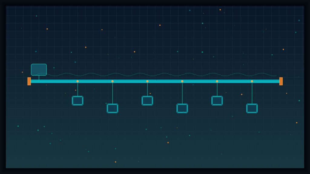
The wrong RS-485 network topology is one of the most common causes of Modbus timeouts, CRC errors, and intermittent sensor dropouts in multi-sensor monitoring installations. Choosing the correct wiring topology — daisy-chain, managed stubs, or repeater-segmented bus — determines whether your sensor network communicates reliably across hundreds of meters or fails during commissioning.
RS-485 (TIA/EIA-485) is the most widely used physical-layer standard for multi-point sensor communication in industrial and environmental monitoring. It uses differential signaling over twisted-pair cable, providing superior noise immunity compared to single-ended interfaces like RS-232. Modbus RTU — the most common sensor-to-data-logger protocol — runs on RS-485 as its default physical layer.
Electrical Limits That Drive Topology Decisions
Before selecting a topology, understand the physical constraints you must design around:
- Maximum distance: TIA/EIA-485 specifies a maximum cable length of 1,200 m (4,000 ft) at lower baud rates. Distance decreases at higher data rates.
- Device count: A standard RS-485 bus segment supports up to 32 unit loads. Modern transceivers with 1/8 unit load rating can support up to 256 physical devices on a single segment.
- Receiver sensitivity: RS-485 receivers detect signals with a differential voltage as low as ±200 mV, providing substantial noise margin for outdoor installations.
These limits directly determine how many sensors you can connect, how far you can run cable, and how the bus must be routed.
RS-485 Network Topology Options for Monitoring Systems
Daisy-Chain (Linear Bus) — The Standard Topology
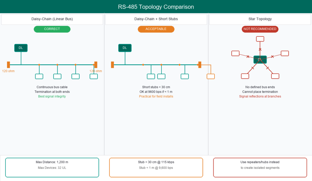
The daisy-chain is the only topology defined by the RS-485 standard. The bus cable enters each device node and exits to the next, forming a continuous path from the first to the last node. Standard 120 Ω termination resistors are placed at both ends of the bus.
Use daisy-chain when:
- Sensors are mounted along a linear path (riverbank, conveyor, pipeline)
- Maximum communication reliability is required
- Sensor spacing is relatively regular
Daisy-Chain with Short Stubs — The Practical Compromise
Field monitoring installations rarely achieve a perfect daisy-chain. Sensors are often mounted meters away from the main bus cable run. Stub (tap) connections off the main bus are acceptable under these conditions:
- Keep stub length as short as possible — ideally under 30 cm at baud rates up to 115,200 bps.
- At low baud rates (≤ 9,600 bps), short stubs under 1 meter typically do not cause significant signal reflections.
- Maximum stub length can be estimated using the cable propagation delay and bit time formula.
Most environmental monitoring systems operate at 9,600 bps, which gives more tolerance for stub length than high-speed industrial applications.
Star Topology — Why It Fails and When Repeaters Fix It
Star topology — where all sensors connect via long individual cables to a central data logger — is not defined by the RS-485 standard and causes signal reflections at every branch point.
The core problems with star topology:
- Correct termination placement is impossible because the bus has multiple endpoints rather than two defined ends.
- Placing termination on each branch creates excessive loading on the driver.
- Signal reflections increase with branch length.
If the physical layout demands a star-like arrangement, the solution is not to force star topology but to use RS-485 repeaters or hubs that regenerate signals. This converts a star physical layout into electrically independent daisy-chain segments.
Repeater-Segmented Networks — Extending Beyond Limits
When sensor count exceeds 32 unit loads or cable distance surpasses 1,200 m, RS-485 repeaters divide the network into independent segments. Each segment supports its own 32 unit loads and 1,200 m distance. Optically isolated repeaters can also help prevent ground loops between monitoring stations at different ground potentials.
Termination and Biasing for Reliable Communication
Incorrect termination — either missing resistors or placing them at intermediate nodes — is one of the most frequent causes of RS-485 communication failures.
Standard termination: Place a 120 Ω resistor at each end of the bus, matched to the cable’s characteristic impedance (typically 100–120 Ω for shielded twisted pair and Cat5).
Fail-safe biasing: Pull-up and pull-down resistors (typically 390–750 Ω) hold the bus in a defined idle state when no device is transmitting, preventing false data reception.
Short-run exception: For bus lengths under approximately 50 m at 9,600 bps, termination resistors may be omitted without significant signal degradation. Note that each 120 Ω termination draws approximately 40 mA, which matters for power budget calculations in solar-powered monitoring stations.
Sensor Planning and Practical Design Rules
Translating electrical rules into implementable monitoring designs:
Modbus address planning: Modbus RTU supports device addresses 1 through 247 on a single bus. The master-slave (client-server) architecture ensures only the master device (data logger) initiates requests, preventing bus collisions. For practical field reliability, limiting each RS-485 bus segment to 8–16 sensors is a common design guideline, even though the standard allows 32.
Cable routing: RS-485 signal cables should enter monitoring enclosures through cable glands and be routed separately from power cables to minimize interference. For complete panel layout guidance, see the outdoor monitoring enclosure design guide.
Cable selection: Use shielded twisted pair with a characteristic impedance of 100–120 Ω. Detailed cable specifications are covered in the sensor cable selection guide.
Common RS-485 Topology Mistakes in Monitoring Installations
Four mistakes that cause the most commissioning failures:
- Star wiring pattern — connecting each sensor via a long individual cable to a central data logger, creating signal reflections and intermittent timeouts.
- Misplaced termination — installing termination resistors at intermediate nodes instead of at both bus ends.
- Excessive stub length — mounting sensors far from the main bus cable without accounting for stub length limits.
- Reversed A/B polarity — swapping the RS-485 A and B connections between devices, causing inverted data interpretation.
If communication problems appear after installation, see the Modbus RTU troubleshooting guide for systematic diagnosis.
When RS-485 Is Not the Right Choice
RS-485 excels for multi-sensor networks at medium to long distances. However, consider alternatives when:
- Sensor count is fewer than 3 at short distances (< 10 m) — a 4–20 mA analog interface may be simpler.
- The application requires galvanic isolation, wireless connectivity, or distances beyond 1,200 m without repeaters.
To understand how RS-485/Modbus RTU connects to the application-layer protocols above it (MQTT, HTTP, Modbus TCP), see the data logger communication protocol comparison.
Argatech’s RS-485 Integration in Monitoring Systems
Fortuna Argatech provides RS-485 Modbus interface solutions and integrates RS-485 sensor communication across monitoring systems including AWLR, AQMS, SPARING, ONLIMO, and weather stations. System design services include data logger configuration, sensor integration, connectivity, and dashboard setup — including RS-485 topology planning tailored to each project’s sensor count and site conditions.
For RS-485 topology design consultation or multi-sensor monitoring project discussion, contact the Argatech team.
Share this article
Share this insight with your team.