Selecting Multipoint Borehole Extensometers for Mining Slope and Dam Safety Monitoring
Surface extensometers often detect slope failures too late. Learn the specifications and working principles of MPBX to detect subsurface shear planes early.
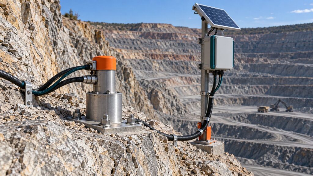
Surface prisms and wire crack meters tell you what already happened. Too late. By the time visible tension cracks split a bench crest, the rock mass is already failing. Haul trucks continue running along the toe while thirty meters underground, weak bedding planes and altered gouge zones are shearing apart. That rupture works upward in silence. Surface survey pegs show flat lines until the final runaway acceleration begins.
Mining regulations do not forgive blind spots. Under Indonesian Kepmen ESDM No. 1827 K/30/MEM/2018 Appendix II, the Chief Inspector of Mines (KTT) must monitor slope stability continuously. Kepdirjen Minerba No. 185.K/37.04/DJB/2019 enforces mandatory TARP slope safety thresholds. Tailings dams face similar rules under ICOLD Bulletin 60, which specifies borehole extensometers to track foundation deformation and internal strain in earth-fill structures.
A Multipoint Borehole Extensometer (MPBX) tackles the subterranean problem directly. It measures axial rock mass movement across multiple discrete depths inside a single borehole. Geotechnical engineers capture internal displacement rates weeks before crest cracks ever appear on the bench.
Anatomy and Working Principle of the MPBX
ASTM D4403-12 and ISRM Suggested Methods govern MPBX operational standards. The instrument measures relative axial displacement between several downhole anchors and a reference head anchored at the collar. The system relies on four primary mechanical components:
- Reference Head: Anchored directly to the borehole collar. Houses displacement transducers, depth micrometer reference seats, and cable junctions.
- Transmitting Rods: Rigid rods connecting downhole anchors to the collar head. They transfer rock displacement mechanically to surface sensors.
- Protective Sleeves: Low-friction PVC or nylon tubing encasing each rod. The sleeve shields the rod from grout and borehole debris, preserving free axial movement.
- Anchor Units: Mechanical wedges, hydraulic bladders, snap-rings, or groutable anchors fixed to the rod tips. Each anchor locks into the borehole wall at a designated depth, pulling or pushing its rod as rock strata shift.
Multi-Depth Architecture: Determining Anchor Quantities
Single-Point Extensometers (SPBX) tell half the story. One anchor sits at the bottom of the borehole. You read cumulative movement between the bottom and the collar. Where did the slide occur? At five meters? Twenty meters? Forty? You cannot tell from an SPBX reading.
Multi-depth arrays fix that limitation. A standard 76 mm to 102 mm borehole holds between two and eight anchor stations spaced along its length. Geotechnical engineers pick anchor elevations directly from diamond drill core logs. Anchors straddle active faults, fractured contacts, and slickensided clay seams.
One operational rule dictates every borehole layout: anchor the deepest station inside competent, immovable bedrock. Drill at least five to ten meters past the lowest anticipated failure plane. That bottom anchor acts as your absolute zero reference datum. If that bottom anchor slips because the driller placed it inside soft shale, your entire displacement dataset is corrupted.
Transmitting Rod Materials: Fiberglass vs Stainless Steel
Picking the wrong rod material introduces severe thermal drift. Direct sunlight beating down on an open-pit collar heats the upper rod sections. Steel expands under heat. The transducer registers displacement, mimicking wall movement even when the rock mass sits completely motionless.
| Mechanical Specification | Fiberglass Rods (FRP) | Stainless Steel Rods |
|---|---|---|
| Elastic Modulus (E) | ~20–40 GPa (Flexible) | ~190–200 GPa (Highly Rigid) |
| Thermal Expansion Coefficient ($\alpha$) | ~6×10^-6 /K (Minimal expansion) | ~16×10^-6 /K (Higher expansion) |
| Material Supply Format | Continuous coiled wire | Segmented threaded rods |
| Optimal Drilling Orientation | Downward vertical holes | Horizontal or upward slanted holes |
| Buckling Risk | Prone to bending in horizontal sleeves | Rigid, resists axial bending |
| Installation Speed | Fast uncoiling from shipping reel | Manual threaded joint assembly |
Continuous fiberglass (FRP) rods excel in vertical down-holes deeper than fifty meters. Shipping reels deliver continuous rod lengths without threaded couplings every three meters. No joints to cross-thread. No bulky couplers to catch on sleeve walls. Fiberglass also handles tropical heat swings smoothly, expanding at less than half the rate of stainless steel.
Stainless steel rods rule horizontal or up-hole underground headings. Fiberglass droops under its own weight when run horizontally inside conduit, rubbing against the sleeve and creating artificial friction. Rigid steel rods, with an elastic modulus near 200 GPa, stay straight. That stiffness eliminates axial sag during tunnel geotechnical surveys where rigs drill extensometer holes into tunnel arches.
Selecting Anchor Types: Groutable, Hydraulic, or Mechanical
An extensometer rod is only as dependable as the anchor locking it to the rock. If an anchor creeps inside the hole, the sensor outputs useless noise.
| Anchor Type | Physical Locking Mechanism | Target Rock Lithology | Field Installation Conditions |
|---|---|---|---|
| Groutable Rebar / Basket | Solid cement-bentonite mortar bond | Weak rock, saprolite, bedded sedimentary layers | Downward vertical holes in open-pit benches. |
| Hydraulic Bladder | Copper or steel sleeve expanded by high-pressure fluid | Fractured hard rock, jointed basalt | Tunnel ribs, underground headings with immediate readout needs. |
| Mechanical Snap-Ring / Wedge | Spring-loaded teeth or wedge expanders driven against rock | Massive, hard competent rock cores | Overhead up-holes where wet grout runs out before curing. |
Groutable anchors dominate open-pit slope installations. Drill crews lower rebar baskets or corrugated anchors down the casing, then backfill the annulus with engineered cement-bentonite grout. The mortar bonds each anchor basket into the surrounding rock mass.
Upward underground drilling demands mechanical or hydraulic anchoring. Gravity dumps wet grout out of overhead boreholes before cement particles can hydrate. Mechanical snap-rings bite directly into competent drill walls. Hydraulic bladders expand under fluid pressure, locking the rod tip into place within minutes.
Calculating Relative Differential and Axial Displacement
Raw transducer readings require reduction into actionable geomechanical metrics. John Dunnicliff’s standard reference (Geotechnical Instrumentation for Monitoring Field Performance, 1993) defines three fundamental calculations:
- Absolute Axial Displacement ($d_i$)
Calculates movement of anchor $i$ relative to the collar reference head:
$$d_i = R_i – R_{i,0}$$
Where $R_i$ is current sensor or micrometer reading, and $R_{i,0}$ is baseline zero reading taken immediately after grout cures. Positive values signify extension. Negative values indicate compression. - Differential Shift Calculation ($\Delta d_{ij}$)
Isolates movement occurring strictly within the rock interval bounded by adjacent anchors $i$ and $j$:
$$\Delta d_{ij} = d_j – d_i$$
When anchor $i$ at twenty meters and anchor $j$ at thirty meters displace equally, $\Delta d_{ij}$ equals zero. The entire rock block translates together. When $\Delta d_{ij}$ spikes, rock between those two anchors is opening or shearing. - Pure Axial Strain Calculation ($\varepsilon_{ij}$)
Normalizes differential movement against original anchor distance ($L_{ij}$):
$$\varepsilon_{ij} = (d_j – d_i) / L_{ij}$$
Plotting strain percentage across each borehole segment reveals the slip boundary. Geotechnical engineers locate the shear plane on cross-sections down to the exact meter.
Cement-Bentonit Grout Design and Sleeve Sealing
Poor grouting practice ruins more MPBX installations than slope movement ever will.
Your grout column must match host ground stiffness. Mix Portland cement, bentonite powder, and clean water to match the elastic modulus of the surrounding formation. A mix curing too stiff creates a rigid structural pillar inside soft saprolite. The slope deforms around it, leaving extensometer anchors unmoved.
Always tremie from the bottom up. Run a rigid HDPE tremie line to the bottom of the borehole. Pump steadily until fresh slurry displaces drilling water and overflows the collar. Pouring grout from the surface traps massive air pockets, leaving rods unsupported and causing anchor slip.
Coupling seals make or break installations. Every threaded joint on PVC or nylon sleeves must be glued or sealed with vulcanizing tape. A pinhole leak lets cement water bleed into the sleeve. Hardened paste against the rod produces a frozen rod. You cannot free a frozen rod. The borehole is dead, forcing an expensive replacement hole on your budget.
Vibrating Wire Transducers and GEOVOS 1000 Telemetry
Potentiometer displacement sensors rarely survive long on harsh mining benches. Resistance drifts with temperature. Moisture rots terminal contacts. Mining excavators and DC haulage trucks generate electromagnetic fields that distort analog voltage signals.
Vibrating Wire (VW) displacement transducers eliminate electrical noise. A steel wire inside the sensor body tensions under rod movement. An electromagnetic coil plucks the wire and reads its resonant frequency in Hertz. Frequency signals travel kilometers through unshielded cables without signal loss or resistance drift.
Sensor cables feed directly into the GEOVOS 1000 smart telemetry system engineered by Fortuna Argatech. Built for remote field deployment, this datalogger performs edge computations on site. It converts frequency data into millimeter displacement rates (mm/day) and evaluates velocities against TARP action levels without requiring cloud connections. If movement crosses an evacuation threshold, onboard relays fire local sirens and strobe lights automatically.
The station transmits records to mine control via long-range LoRa radio or industrial 4G modems. Pit benches experience severe lightning activity. Multi-stage heavy-duty lightning surge protection diverts voltage spikes to ground before electrical transients reach datalogger circuitry or transducer coils.
Maintaining the Lifespan of Monitoring Instruments
Geotechnical instrumentation requires systematic field audits. Transducer calibrations drift over time. Technicians must open the reference head quarterly and take manual depth micrometer readings against rod stems. Compare micrometer values with automated electronic outputs. Document each calibration in mine logbooks to satisfy KTT regulatory audits under Kepmen ESDM 1827/2018.
Protect surface collars from heavy mine traffic. Blasted flyrock or a Caterpillar 777 haul truck tire will crush an exposed instrument station in seconds. Pour a reinforced concrete footing around the borehole collar. Bolt a lockable, heavy-wall steel cover over the transducer assembly.
Reliable slope hazard assessment demands multi-sensor correlation. Combine MPBX subsurface axial movement with lateral shear profiles from an automatic In-Place Inclinometer. Track hydrostatic pore pressures using a Vibrating Wire Piezometer to identify groundwater spikes that trigger slope slides. Contact the Fortuna Argatech engineering team for borehole sensor layout design, grouting protocols that avoid frozen rods, and GEOVOS datalogger telemetry tied into 24/7 mine stability monitoring networks.
Share this article
Share this insight with your team.
Related Articles
Similar topics from the same category.
Monitoring station OPEX budget planning guide covering five cost pillars, cross-station comparison, hidden costs, and a modular worksheet for annual budgeting.

8 mandatory monitoring criteria for PROPER Blue rating under PermenLH 7/2025: SPARING, AQMS, B3, waste, peatland, mining, and SIMPEL audit.

Compare TDR and FDR soil moisture sensor principles, dielectric calibration limits for tropical peat, and multi-depth telemetry integration via GEOVOS 1000.