How to Size and Select an Electromagnetic Flow Meter for Closed-Pipe Wastewater SPARING Compliance
How to size an electromagnetic flow meter for wastewater: velocity window, liner-electrode materials, grounding, and SPARING integration.
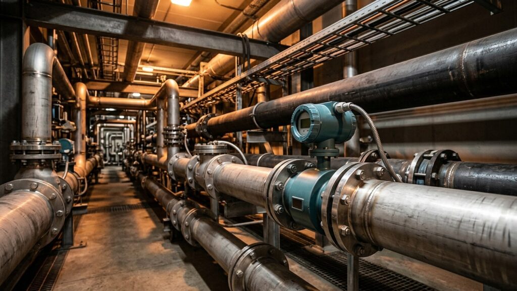
Buying an electromagnetic flow meter that matches your pipe size is the single most common, and most expensive, mistake in industrial wastewater metering. A DN200 magmeter bolted onto a DN200 outfall running at half its design flow pushes fluid velocity below 0.2 m/s. At that speed, the sensor’s induced voltage drowns in electrical noise. Solids settle on the electrodes. Your readings drift wildly. Meanwhile, Indonesia’s SPARING regulation (Permen LHK No. P.80/2019, amending P.93/2018) demands continuous effluent flow measurement within ±10% accuracy across all twelve mandatory industrial sectors.
This guide walks through the engineering decisions that determine whether a magmeter installation actually meets that accuracy threshold: hydraulic velocity sizing, wetted-part material selection, mechanical installation rules, grounding ring requirements for plastic pipes, and signal integration to the SPARING telemetry chain.
Measurement Principle: Faraday’s Law in a Full-Bore Pipe
An electromagnetic flow meter works on Faraday’s law of electromagnetic induction. Conductive liquid flowing through a magnetic field generates a voltage proportional to its average velocity. The sensor has no moving parts. No obstructions sit in the flow path. No pressure taps, no orifice plates, no mechanical rotors. You get zero head loss and zero risk of clogging from suspended solids, which matters enormously in wastewater loaded with TSS, fibers, and sludge.
The catch is conductivity. The fluid needs a minimum electrical conductivity of 5 µS/cm. Industrial wastewater typically runs between 50 and 5,000 µS/cm, so nearly every effluent stream clears this bar without trouble. Pure hydrocarbons, deionized water, and non-conductive solvents fall outside the magmeter’s operating envelope entirely.
Hydraulic Sizing: Why You Cannot Match the Pipe Diameter
Sizing a magmeter means sizing for velocity, not pipe diameter. The optimal flow velocity inside the sensor tube is 1–3 m/s under normal operating conditions. Drop below 0.5 m/s and the signal-to-noise ratio falls apart. Solids start settling on the liner and electrode surfaces, fouling the measurement. Exceed 5 m/s (or 3 m/s in abrasive slurry service) and you risk premature liner erosion.
Here is where the oversizing problem hits. Your effluent pipe is DN200, but the actual daily flow produces only 0.3 m/s through that cross-section. The magmeter reads garbage. The fix: reduce the sensor size one or two nominal steps below the pipe diameter. Install a DN150 or DN100 magmeter using concentric reducers on both sides, tapered at no more than 8° per side to keep turbulence low and additional pressure drop minimal.
Every wastewater treatment plant does this. A reduced-bore installation pushes the fluid velocity back into the 1–3 m/s sweet spot. Measurement stability improves. Low-flow turndown gets better. Pumps stay happy.
Application Scenario: A palm oil mill effluent outfall runs DN200 pipe at an average flow of 40 m³/h. At DN200, the cross-sectional velocity is approximately 0.35 m/s, too slow for reliable measurement. Step down to a DN100 magmeter with concentric reducers and the velocity jumps to roughly 1.4 m/s. Right in the target range.
Wetted-Part Material Selection: Matching Liner and Electrode to Your Effluent
The liner and electrodes are the only components that touch the process fluid. Get the materials wrong and you end up with chemical attack, liner delamination, or electrode pitting. Any one of those kills a sensor that probably ate a major chunk of your instrumentation budget.
Liner Materials
| Liner | Chemical Resistance | Abrasion Resistance | Max Temp | Best Suited For |
|---|---|---|---|---|
| PTFE | Excellent: resists concentrated acids, strong alkalis, organic solvents | Moderate | 180 °C | Petrochemical effluent, aggressive chemical waste, high-temperature discharge |
| Hard Rubber (Ebonite) | Good: handles common inorganic chemicals | Excellent | 80 °C | General WWTP service, municipal wastewater, palm oil mill effluent (POME) |
| PFA | Excellent: comparable to PTFE | Good, with superior vacuum resistance | 180 °C | Hot acid service, vacuum conditions in suction-side piping |
| Polyurethane | Limited: weak against strong acids and solvents | Highest of all liners | 60 °C | Mining acid drainage with heavy sediment, sand slurry, cement plants |
| EPDM | Good for neutral/alkaline media, incompatible with oils and hydrocarbons | Moderate | 120 °C | Cooling water, neutral secondary effluent, clean water |
Electrode Materials
| Electrode | Strength | Weakness | Typical Application |
|---|---|---|---|
| SS 316L | Low cost, adequate for non-corrosive media | Pitting corrosion when chloride exceeds 200 ppm | Domestic wastewater, clean industrial water |
| Hastelloy C-276 | Industry default: resists oxidizing and reducing environments, chloride, dilute mineral acids | Higher cost | Chemical plant effluent, textile dyeing waste, mixed industrial wastewater |
| Titanium | Excellent against chloride, brine, and oxidizing acids (HNO₃) | Fails against reducing acids (HCl, H₂SO₄) | Coastal facilities, brackish water, saline wastewater |
| Platinum / Tantalum | Near-universal resistance to concentrated acids | Highest cost | Concentrated acid processes, extreme corrosion environments |
For most Indonesian industrial wastewater applications (palm oil, textile, food and beverage), a Hard Rubber liner with Hastelloy C-276 electrodes gives you the best balance of durability, abrasion resistance, and chemical compatibility. Switch to PTFE liner when handling aggressive chemical waste or temperatures above 80 °C.
Installation Requirements: Straight Run, Full Pipe, and Electrode Orientation
A perfectly specified magmeter still produces bad data if the piping layout violates basic hydraulic rules.
Straight run. Provide a minimum of 5 pipe diameters (5D) of straight, unobstructed pipe upstream and 2 diameters (2D) downstream of the sensor. No elbows, valves, reducers, or tees within those lengths. This gives the velocity profile enough distance to become symmetrical before reaching the electrodes.
Full-pipe condition. The magmeter calculates flow using the full cross-sectional area. A partially filled pipe causes massive over-reporting because the instrument assumes the tube is 100% full. If your outfall is a gravity line, either install the sensor in a vertical section with upward flow or build a siphon arrangement that guarantees full-pipe conditions.
Vertical upward flow. The single best installation orientation. Gravity keeps the pipe full. Air bubbles migrate upward and out of the measurement zone. Solids cannot settle.
Electrode orientation on horizontal pipe. When horizontal mounting is unavoidable, orient the electrodes at 3 o’clock and 9 o’clock (horizontal plane). Never at 12 and 6. Gas pockets collect at the top (12 o’clock) and sediment collects at the bottom (6 o’clock). Both insulate the electrode from the fluid.
Empty pipe detection. Modern magmeters include a detection circuit that senses when the liquid level drops below the electrodes. The circuit locks the output to zero and triggers a diagnostic alarm. No phantom flow readings during shutdown or low-flow periods.
Grounding Rings: Mandatory on HDPE, PVC, and FRP Pipe
Faraday’s induced voltage is measured in microvolts. The measurement reference is the electrical potential between the fluid and the sensor body. On metallic pipe, the fluid is naturally grounded through the pipe wall. On non-metallic pipe (HDPE, PVC, FRP, or rubber-lined steel), that electrical connection disappears. The fluid floats. Stray electrochemical currents generate noise that overwhelms the flow signal.
The fix is grounding rings: metal discs (typically 316L stainless or Hastelloy, matched to the electrode material) clamped between the pipe flanges and the sensor flanges on both sides. They make physical contact with the fluid and establish the zero-potential reference.
Bond the cable from both grounding rings and the sensor body to a dedicated instrument earth ground with a resistance of 5 Ω or less. In high-noise industrial areas, aim for 1 Ω or below. Never tie the sensor ground to motor power earth or lightning protection ground. The electrical noise from those systems will wreck your flow signal.
SPARING Telemetry Integration: Pulse, 4-20 mA, and Modbus to GEOVOS 1000
Under Permen LHK No. P.80/2019 (amending P.93/2018, Appendix III), Indonesian industrial facilities must continuously record effluent flow rate and cumulative daily volume, meeting the ±10% accuracy mandate. The magmeter produces the measurement. The data logger captures, totalizes, and transmits it.
Three signal interfaces connect the magmeter transmitter to the data logger:
- Scaled pulse output: each pulse represents a fixed volume (e.g., 1 pulse = 0.1 m³). The data logger counts pulses and accumulates the totalizer. This method is the most accurate for volume totalization because it transmits absolute physical quantities with no analog-to-digital conversion drift.
- 4-20 mA analog: represents instantaneous flow rate (m³/h). Useful for real-time trending and diagnostics, but subject to minor ADC drift over long cable runs. Supports NAMUR NE 43 live-zero fault diagnostics.
- RS-485 Modbus RTU: digital communication that delivers instantaneous flow, forward/reverse totalizer values, and empty-pipe alarm status simultaneously over a single shielded twisted-pair cable.
The GEOVOS 1000 industrial data logger from Fortuna Argatech supports all three interfaces: a high-speed pulse counter input, isolated 4-20 mA analog input, and RS-485 Modbus RTU port. Its internal totalizer algorithm accumulates daily effluent volume and formats the telemetry string for automatic transmission to the KLHK SPARING server.
For procurement specification documents, specify the magmeter output type, scaling factor, and cable requirements alongside the data logger model. This keeps integration clean during factory acceptance testing (FAT) and site commissioning (SAT).
Getting It Right the First Time
An electromagnetic flow meter is the industry standard instrument for closed-pipe wastewater measurement, but only when the sizing, materials, installation, grounding, and telemetry integration are done correctly. Size for velocity, not for pipe diameter. Match the liner and electrodes to your specific effluent chemistry. Provide straight runs and guarantee full-pipe conditions. Install grounding rings on every non-metallic pipe section. Wire the output signal properly to a data logger that meets SPARING reporting requirements.
Fortuna Argatech provides integrated SPARING monitoring solutions: calibrated electromagnetic flow meters, fabricated reducer spool pieces with grounding kits, GEOVOS 1000 data logger integration, on-site accuracy verification, and automated telemetry to the KLHK server.
Share this article
Share this insight with your team.
Related Articles
Similar topics from the same category.
Monitoring station OPEX budget planning guide covering five cost pillars, cross-station comparison, hidden costs, and a modular worksheet for annual budgeting.

8 mandatory monitoring criteria for PROPER Blue rating under PermenLH 7/2025: SPARING, AQMS, B3, waste, peatland, mining, and SIMPEL audit.

Compare TDR and FDR soil moisture sensor principles, dielectric calibration limits for tropical peat, and multi-depth telemetry integration via GEOVOS 1000.