Monitoring Structural and Mining Slope Rotational Deformation Using Biaxial Tiltmeter Sensors
Discover how biaxial tiltmeter sensors detect rotational deformation on retaining walls, dams, and open-pit mining slopes with sub-millimeter precision.
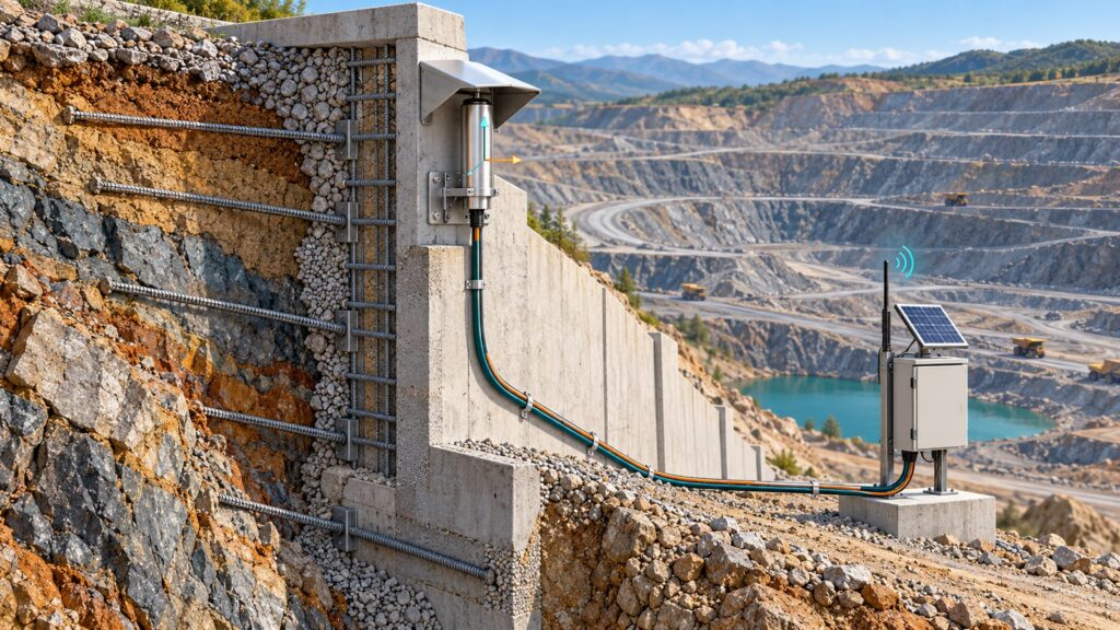
Rock slopes and concrete retaining walls do not fail without warning. Long before concrete shears or a bench gives way, the structure rotates. It tilts. Fractions of a degree. Routine surface surveys miss it every single time. A survey crew running monthly total station traverses catches translational shift well enough, but base rotation happens quietly long before a survey prism moves enough to trigger an alarm. A tiltmeter sensor bolted directly to the substrate catches that angular shift in real time. It reads down to thousandths of a degree. It feeds the datalogger before the first tension crack even opens on the bench crest above.
Anatomy of Rotational Deformation: Why Early Detection Demands Angular Measurement
Rotational failures follow predictable physics. Retaining walls pivot on their footings when lateral earth pressure overcomes the restoring moment. Bridge piers lean under scour settlement. Dam crests deform when seepage softens the downstream shell. On stepped open-pit benches, jointed rock columns lean outward around a basal pivot, classic toppling failure.
In every case, the earliest detectable symptom is angular rotation, not linear slip. A wall rotating just 0.05 degrees at its foundation creates less than 3 mm of crest movement over a 4-meter height. A total station shooting from 200 meters away will not flag that. A biaxial tiltmeter catches it instantly.
Indonesian mining regulation Kepmen ESDM No. 1827 K/30/MEM/2018 legally requires geotechnical slope monitoring on open-pit walls and retaining structures to catch instability before ground fails. The rule does not name a specific brand or sensor, but basic mechanics makes tiltmeters and extensometers the front line for retaining walls, bridge piers, and steep rock faces where toppling governs the failure mode.
Transducer Physics: MEMS, Vibrating Wire, and Electrolytic
Not every tiltmeter works the same way under the hood. Three transducer types dominate the market, each with distinct trade-offs.
MEMS Biaxial Accelerometer. A micro-machined proof mass reacts to the DC pull of gravity. As the housing tilts, the mass shifts between internal capacitive plates, outputting a voltage tied to the sine of the tilt angle. Measurement range runs wide, from ±5 degrees up to ±90 degrees. Resolution reaches 0.001 degrees (0.017 mm/m, roughly 3.6 arcseconds). Power consumption stays below 10 mA when active and drops under 50 microamps in sleep mode. That tiny power footprint makes MEMS the clear winner for battery-fed wireless IoT nodes and solar-powered stations in remote mining pits.
Vibrating Wire Pendulum. A pendulum mass tensions a steel wire inside the housing. Tilt shifts the pendulum, changing the wire tension. A magnetic coil plucks the wire and reads its resonant frequency. Frequency squared maps directly to tension, yielding an exact tilt angle. Long-term zero drift stays below 0.02 mm/m per year. Even better, the frequency signal ignores cable resistance across runs stretching 1 to 2 kilometers. For permanent installations buried in dams or deep mine walls with long cable trenches, vibrating wire remains rock solid.
Electrolytic Bubble. A sealed glass vial holds conductive fluid and a gas bubble. Electrodes arranged in an AC Wheatstone bridge track the bubble position as the unit tilts. Resolution is extreme, dipping below 0.1 arcseconds (<0.0005 mm/m). But the measurement range is tiny, barely ±0.5 to ±3 degrees. Fluid viscosity also swings wildly with temperature. That makes electrolytic sensors temperamental outdoors and largely useless for baking tropical mine sites.
| Parameter | MEMS Biaxial | Vibrating Wire | Electrolytic |
|---|---|---|---|
| Sensing principle | Capacitive gravity acceleration | Pendulum resonant wire frequency | Conductive electrolyte bubble bridge |
| Measurement range | ±5° to ±90° | ±5° to ±15° | ±0.5° to ±3° |
| Resolution | 0.001° (0.017 mm/m) | 0.05 mm/m (~8 arcsec) | <0.1 arcsec (<0.0005 mm/m) |
| Long-term zero stability | Moderate (needs baseline check) | Superior (<0.02 mm/m/year) | Poor without thermal modeling |
| Power consumption | <10 mA active, <50 µA sleep | Pluck-and-read, low duty cycle | Continuous AC excitation |
| Cable length immunity | Moderate (voltage degrades) | Excellent (frequency signal, >1 km) | Poor (AC bridge sensitive) |
| Typical application | Wireless IoT nodes, solar stations | Dam crests, long-cable mine slopes | Lab-grade SHM, cleanrooms |
Choose based on site realities. Need fast wireless deployment in a remote pit? Run MEMS. Need permanent zero stability over a decade across miles of copper wire? Bolt down vibrating wire. If you also need deep subsurface displacement profiling, pair surface tilt with a downhole extensometer system.
Converting Angles to Physical Displacement: ISO 18674-3 Standards
An angle in degrees or arcseconds does not help an operations manager decide whether to clear an excavator. You have to convert tilt into lateral displacement. The math is basic trigonometry: Δd = L × sin(θ), where L is the gauge length and θ is the measured angle. For small angles, sin(θ) equals θ in radians. For field shorthand: 1 mm/m equals 0.0573 degrees or 206.265 arcseconds.
The ISO 18674-3:2017 standard sets strict rules for geotechnical tilt sensors. Two details matter in the field. First, the 24-hour baseline test: an undisturbed sensor on a reference surface must hold stability within 0.1 mm/m over a full day before installation. Second, the 180-degree reversal check: flip the sensor exactly 180 degrees on its mounting plate, take readings both ways, and average them. That cancels any internal sensor zero offset before logging starts.
When a single tiltmeter leaves blind spots across a long diaphragm wall or tunnel crown, link them into a Tilt Beam chain. Mount rigid 1- to 3-meter beams end-to-end along the wall, each carrying its own tiltmeter. Integrating the angular changes down the line reconstructs a complete horizontal deflection curve from base to crest.
Killing Tropical Thermal Drift
Anyone who has bolted a bare tiltmeter to an Indonesian concrete retaining wall knows the headache. The morning baseline looks clean. By 2:00 PM, the sensor reports an alarming angular jump. By midnight, it settles right back. The wall did not move. The tropical sun baked it.
Equatorial surfaces easily swing from 20 degrees Celsius at dawn to over 50 degrees Celsius by midday. That 30-degree thermal shock causes two distinct errors. First, differential expansion bows the concrete substrate, creating real but temporary tilt that has nothing to do with slope instability. Second, the sensor electronics drift internally under heat. Together, these effects generate dozens of arcseconds of apparent tilt. That is more than enough to trigger false emergency alarms.
Stop thermal noise with three layers of defense:
- Insulated sunshields. Cover the sensor housing with an insulated metal hood to block direct solar radiation and slow thermal spikes.
- Thermal decoupling plates. Use standoffs or insulating gaskets between the mounting plate and the concrete to kill conductive heat transfer.
- Polynomial temperature correction. Log the internal thermistor reading alongside tilt. Run a polynomial calibration curve in the datalogger firmware to strip electronic drift out of the raw signal in real time.
A thorough site survey maps sun angles and shading before you drill anchor holes.
Mechanical Mounting: Aligning X-Y Axes and Anchoring
A biaxial tiltmeter outputs two channels: X-axis tilt and Y-axis tilt. How you physically orient those axes dictates whether your data means anything.
Align the X-axis perpendicular to the primary failure direction. On a retaining wall, point the X-axis straight out from the wall face. Any outward tilt registers directly on channel X. The Y-axis runs parallel along the wall face, logging transverse tilt and differential settlement.
Anchor the plate into solid material. Use 316 stainless steel expansion bolts or chemical epoxy studs set into structural concrete or unweathered rock. Never anchor into plaster, cosmetic shotcrete, or crumbling weathered rock. A loose anchor measures surface flaking, not structural movement.
Torque the bolts to spec. Check the plate with a precision spirit level during mounting. Log that initial mechanical offset at commissioning and zero it out in software.
TARP Thresholds and Real-Time Telemetry with GEOVOS 1000
Total tilt tells you where the wall sits today. Tilt velocity tells you when it will fail. An effective Trigger Action Response Plan (TARP) keys on angular rate of change (degrees per day or mm/m per week), not just cumulative tilt. A wall leaning 0.1 degrees over five years is fine. That same wall moving 0.1 degrees in 48 hours is heading for collapse.
Under Kepmen ESDM No. 1827 K/30/MEM/2018, mining operations run four-tier TARP matrices:
| TARP Level | Condition | Action |
|---|---|---|
| Green (Normal) | Tilt stable, rate under 0.005°/day | Routine logging at standard scan rate |
| Yellow (Alert) | Cumulative tilt rising, rate 0.005° to 0.02°/day | Step up scan frequency, inspect site physically |
| Orange (Alarm) | Rate hits 0.02° to 0.05°/day for 48 hours | Restrict equipment access, mobilize geotechnical engineers |
| Red (Emergency) | Rate exceeds 0.05°/day or sudden acceleration | Clear the pit floor, shut down operations immediately |
Calibrate these numbers against site-specific slope stability models. Generic thresholds get people hurt.
The Fortuna Argatech GEOVOS 1000 Datalogger handles multi-channel tilt inputs across RS-485 Modbus RTU, 4-20 mA, and wireless LoRaWAN. Its edge engine calculates trigonometric displacement, filters out transient equipment vibration, and checks TARP limits on every scan. When a reading breaches an alarm threshold, the unit pushes instant alerts over cellular or satellite telemetry without waiting for scheduled batch uploads.
If you are designing an automated early warning network, contact Fortuna Argatech for engineering support on sensor selection, thermal shield design, and TARP integration.
Share this article
Share this insight with your team.
Related Articles
Similar topics from the same category.
Monitoring station OPEX budget planning guide covering five cost pillars, cross-station comparison, hidden costs, and a modular worksheet for annual budgeting.

8 mandatory monitoring criteria for PROPER Blue rating under PermenLH 7/2025: SPARING, AQMS, B3, waste, peatland, mining, and SIMPEL audit.

Compare TDR and FDR soil moisture sensor principles, dielectric calibration limits for tropical peat, and multi-depth telemetry integration via GEOVOS 1000.