Lightning Protection for Monitoring Stations: From Grounding to Surge Arresters
A guide to lightning protection monitoring stations: the complete chain from air terminal and grounding to SPDs on power, signal, and communication lines.
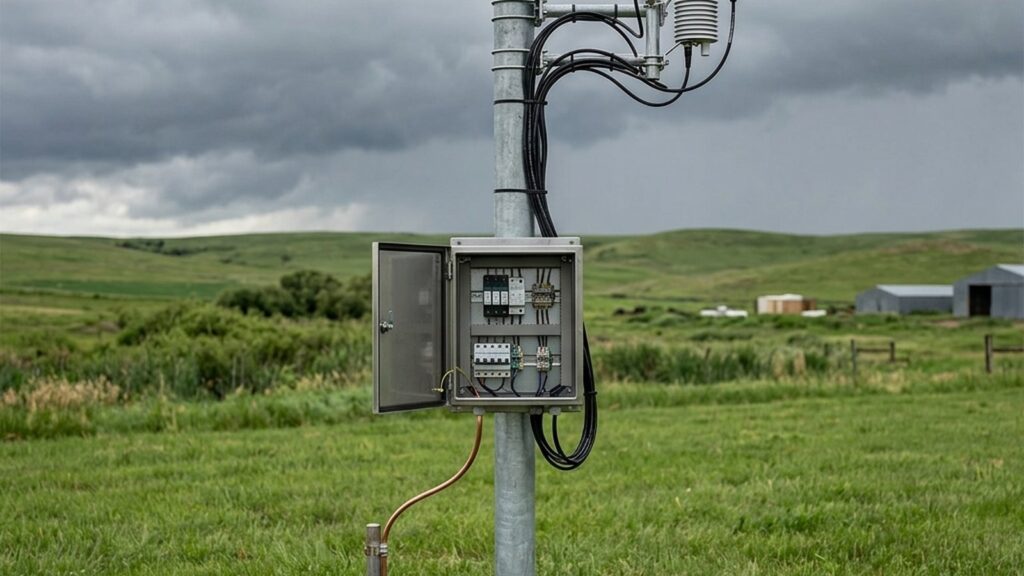
Installing a grounding rod on a monitoring station pole is necessary but not sufficient. The lightning protection monitoring stations actually need is a complete chain — from an air terminal at the top of the mast to an earth electrode in the ground, plus surge protective devices (SPDs) on every cable entering the equipment enclosure.
Indonesia’s tropical maritime climate produces high lightning activity. Environmental monitoring stations such as weather stations, AWLR, AQMS, extensometers, SPARING, and ONLIMO systems are typically installed in exposed locations — riverbanks, rooftops, mine slopes, or industrial stacks — placing them directly in the path of lightning strikes and induced surges.
This article explains the protection chain and how each layer works together to protect sensors, dataloggers, and communication systems.
How Lightning Damages a Monitoring Station
Lightning can produce peak currents exceeding 200 kA. Damage to monitoring equipment occurs through three main mechanisms:
- Direct strike — lightning current hits the mast, antenna, or sensor directly.
- Conducted surge — lightning current travels along power cables, sensor signal cables, or communication cables connected to the enclosure.
- Ground potential rise — a difference in ground potential between equipment grounding points when lightning current flows into the earth.
The second and third mechanisms are frequently underestimated. A lightning strike hitting the ground or a structure near the station can induce voltage surges on RS485 or 4-20 mA cables or power lines without striking the station directly. Low-voltage electronic components — dataloggers, modems, and sensors — can be damaged by surges that are small compared to the full lightning current.
The Protection Chain: Four Layers That Work Together
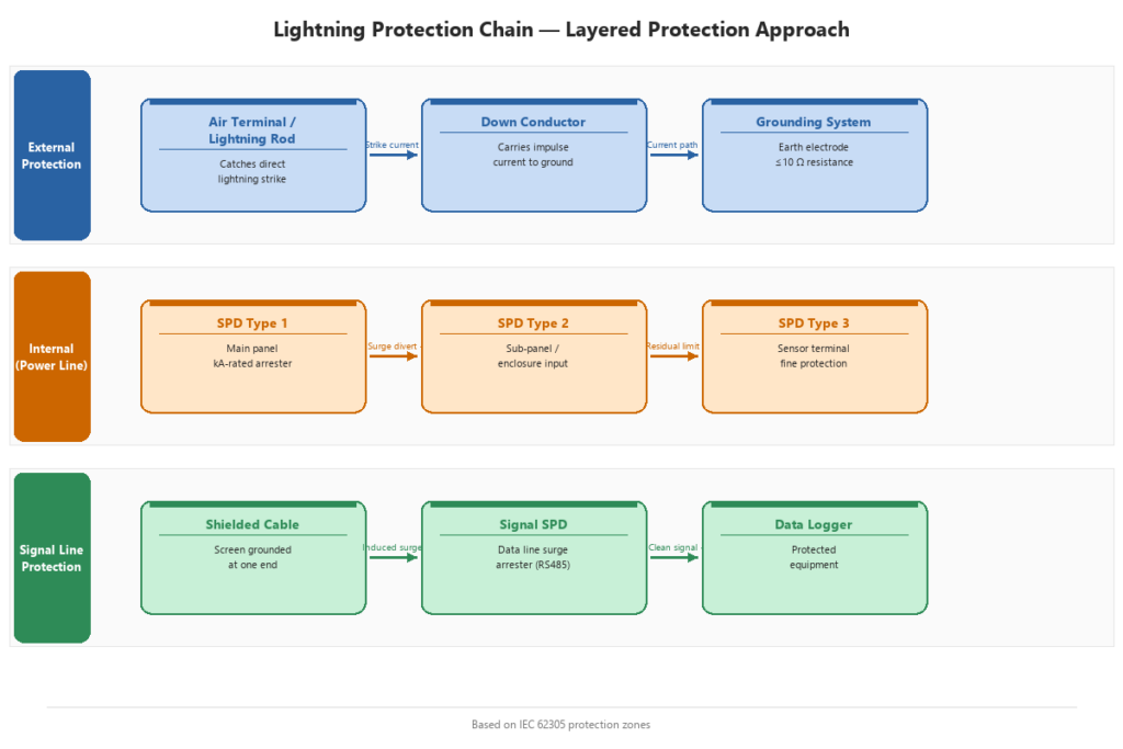
The international standard series IEC 62305 establishes a lightning protection framework consisting of external and internal protection systems. For a monitoring station, all four layers should be planned as an integrated system:
1. Air Terminal
A lightning rod or finial is installed at the highest point of the structure — typically at the top of the sensor mast or antenna. Its function is to provide a controlled strike point so that lightning current flows through a designed path rather than through the equipment.
2. Down Conductor
The down conductor connects the air terminal to the earth electrode, providing a low-impedance path for lightning current to reach the ground. IEC 62305-3 specifies the material, cross-section, and routing requirements for down conductors.
3. Earth Termination
The earth electrode dissipates lightning current into the ground. IEC 62305-3 recommends an earth resistance of 10 Ω or less where practicable. The achievable value depends on local soil resistivity, which should be measured during the site survey.
4. Surge Protective Devices (SPDs)
SPDs limit transient overvoltages on conductive paths entering the enclosure. This layer protects electronic equipment from surges conducted through cables — the damage mechanism most commonly overlooked in monitoring installations.
SPDs on Every Path Into the Enclosure
The principle from IEC 62305-4 is to install SPDs on every conductive path that penetrates the enclosure boundary. At a monitoring station, these paths include:
- AC/DC power input — from grid supply, generator, or solar charge controller to the datalogger and modem.
- Sensor signal cables — RS485 or 4-20 mA cables from sensors to the datalogger. Signal-line SPDs must match the signal voltage, current, and protocol characteristics to avoid interfering with measurement data.
- Communication cables — Ethernet or other data cables entering the enclosure.
- Antenna feedlines — coaxial cable from the cellular or radio antenna to the modem. A coaxial SPD is installed at the cable entry point.
SPDs are available in different types or classes matched to their installation location relative to the service entrance. They contain sacrificial components — metal-oxide varistors (MOVs) or gas discharge tubes — that absorb surge energy and can degrade after repeated surge events.
A common gap in monitoring installations is fitting SPDs on the power line while leaving the sensor signal and antenna paths unprotected. A voltage surge entering through tens of meters of RS485 cable from a field sensor can destroy the datalogger’s communication port even when the power line is protected.
Grounding That Works in the Field
Grounding quality determines whether the other protection layers function effectively. Practical considerations include:
- Measure soil resistivity on site — soil type, moisture content, and geological conditions affect the achievable earth resistance. Rocky or dry soil requires a different electrode configuration than moist soil.
- Select appropriate electrodes — copper rods, plates, or electrode combinations can be used depending on soil conditions and target resistance.
- Bond all metal parts to a single earth reference — the mast, enclosure, solar panel bracket, and DIN rail inside the panel should all be connected to the same earthing system (equipotential bonding) to prevent potential differences.
- Measure earth resistance periodically — soil conditions change with the seasons. Decreasing soil moisture during dry periods can increase earth resistance.
Indonesian building regulations through PP 36/2005 (implementing UU 28/2002 on Buildings) include lightning protection provisions for buildings. For monitoring station structures in open areas, IEC 62305 principles should be applied according to the structure type and site conditions.
Inspection and Maintenance After Installation
Lightning protection is not an install-and-forget system. Components requiring periodic inspection include:
- Earth resistance — measure at least annually and after any detected lightning event. Seasonal changes affect resistance values.
- SPD status — check the status indicators on each SPD. Most SPDs have a visual indicator (green/red) showing whether the sacrificial component is still functional or needs replacement.
- Conductor condition — inspect down conductors, connections, and clamps for corrosion, mechanical damage, or loosened connections.
- Post-storm checks — after a lightning event near the site, inspect all protection components and test monitoring equipment functionality.
The WMO CIMO Guide (WMO-No. 8) also addresses lightning protection requirements for meteorological observation stations, providing a relevant supplementary reference for environmental monitoring stations.
What to Specify When Planning a New Station
When planning a new monitoring station, include lightning protection specifications in the design documentation. The following checklist can help:
| Component | What to specify |
|---|---|
| Air terminal | Type, height, and position on the structure |
| Down conductor | Material, cross-section, routing path |
| Earth electrode | Type, depth, target resistance |
| Power-line SPD | Type, working voltage, discharge capacity |
| Signal-line SPD | Compatibility with RS485/4-20 mA, signal voltage |
| Antenna SPD | Connector type, operating frequency |
| Equipotential bonding | Points connected to the earthing bus |
| Testing | Method and schedule for resistance measurement |
Fortuna Argatech generally equips open-area installations with grounding systems and surge arresters to protect electronic devices inside the datalogger. The specific lightning protection requirements depend on site conditions, structure type, and the level of lightning exposure identified during the site survey.
References
- International Electrotechnical Commission. IEC 62305-1: Protection against lightning – Part 1: General principles, Edition 2.0, 2010.
- International Electrotechnical Commission. IEC 62305-3: Protection against lightning – Part 3: Physical damage, Edition 2.0, 2010.
- International Electrotechnical Commission. IEC 62305-4: Protection against lightning – Part 4: Electrical and electronic systems, Edition 2.0, 2010.
- World Meteorological Organization. WMO-No. 8: Guide to Instruments and Methods of Observation (CIMO Guide), 2023.
- Government of Indonesia. PP No. 36 Tahun 2005 on Implementation of UU No. 28 Tahun 2002 on Buildings, 2005.
Share this article
Share this insight with your team.
Related Articles
Similar topics from the same category.
Poor weather station placement can cause 50% data bias. Learn the WMO-No. 8 and Indonesian BMKG siting standards for AWS sensors in industrial and mining sites.
Explore a technical engineering comparison between solid-state ultrasonic anemometers and mechanical cup-and-vane sensors for industrial weather stations.

Technical guide to conductivity sensors: comparing toroidal (inductive), 2-electrode, and 4-electrode contacting probes for industrial water and wastewater.